inglewoodpete
Senior Member
Configuring your new LCD can be challenging task, particularly if your model does not use a serial interface.
The attached code simplifies the task by specifying a universal piece of executable code with a few, separate lines of "Symbols" to define the function of each pin. The code is independent of hardware constraints: gone are the days where you have to connect specific pins to each other for the LCD to work!
The code is an ideal way to do an initial test of a new PCB or stripboard design incorporating an LCD.
This code is designed to run the parallel LCD in 4-bit mode. All you have to do is connect a total of 8 wires between your PICAXE and the parallel LCD module. This assumes that you have an LCD module that runs at the same voltage as the PICAXE - usually this is 4.5 or 5 volts.
Edit: Some LCD boards the R/W pin tied to 0v to ensure that your can only write to the LCD. If your LCD module does not tie this line low already, then you will need to do this. Refer to post #6 for options. The R/W pin is pin 5 on the three different LCD connectors that I'm aware of.
Next adjust the 8 Symbol commands to point to the outputs that you have connected your LCD inputs to. Note that the actual leg numbers on the chip will differ according to the model you are using. Refer to Manual 1 - "Getting Started" for pinout diagrams.
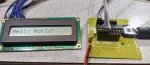
Save the code and download it to your PICAXE. If you have configured everything correctly, you shoud see the "Hello World!" message on your LCD.
The attached code simplifies the task by specifying a universal piece of executable code with a few, separate lines of "Symbols" to define the function of each pin. The code is independent of hardware constraints: gone are the days where you have to connect specific pins to each other for the LCD to work!
The code is an ideal way to do an initial test of a new PCB or stripboard design incorporating an LCD.
This code is designed to run the parallel LCD in 4-bit mode. All you have to do is connect a total of 8 wires between your PICAXE and the parallel LCD module. This assumes that you have an LCD module that runs at the same voltage as the PICAXE - usually this is 4.5 or 5 volts.
Edit: Some LCD boards the R/W pin tied to 0v to ensure that your can only write to the LCD. If your LCD module does not tie this line low already, then you will need to do this. Refer to post #6 for options. The R/W pin is pin 5 on the three different LCD connectors that I'm aware of.
- Two of the wires are obviously the Ground or 0v line and the +5v line.
- The 4 data lines (d4 - d7) and 2 control wires (Enable and Register Select) connect to any output pin that you have free on your PICAXE.
Next adjust the 8 Symbol commands to point to the outputs that you have connected your LCD inputs to. Note that the actual leg numbers on the chip will differ according to the model you are using. Refer to Manual 1 - "Getting Started" for pinout diagrams.
Save the code and download it to your PICAXE. If you have configured everything correctly, you shoud see the "Hello World!" message on your LCD.
Code:
'Simple, flexible test routine for parallel LCDs (Tested on a 16 char x 2 row LCD)
'Should work on any PICAXE with 14 or more legs.
'#PICAXE 28X2    'Change to suit your processor
'
' **** Pins ****
'
' 4-bit mode: Uses a total of 8 wires between the PICAXE and LCD:
'              0v, +5v, Register Select and LCD Enable
'              4 data wires: Pins 4 to 7 on the LCD
'
' Flexible software:
'   (practically*) any pin of the PICAXE can connect to any of the 6 control pins of the LCD
'    *Note that leg 4 on the following PICAXEs is input-only and can't be used as an output
'     Don't use 14M2/C.3; 18M2/C.5; 20M2/C.6 and 20X2/C.6
'
'   After wiring up the LCD to the PICAXE (Data transfer is via pins 4 to 7 on the LCD),
'     define the following symbols to their function.
'  Note that the 4 data pins must be addressed in 2 two different ways
'
Symbol oLCDpin4   = outpinB.1   'B.1 for writing to the output pin directly
Symbol oLCD4      = B.1
'
Symbol oLCDpin5   = outpinB.5   'B.5 for writing to the output pin directly
Symbol oLCD5      = B.5
'
Symbol oLCDpin6   = outpinB.6   'B.6 for writing to the output pin directly
Symbol oLCD6      = B.6
'
Symbol oLCDpin7   = outpinB.7   'B.7 for writing to the output pin directly
Symbol oLCD7      = B.7
'
Symbol oLCDRS     = C.0         'C.0 Register select: Low for Commands, High for Characters

Symbol oLCDEn     = C.1         'C.1 Enable pin. Default condition is low. Pulse High to input data.
'
'   There is no need to touch the code of the test routine!!
'   After defining the above symbols, the code should compile, load and run.  Simple!
'
'       EEPROM and Message Pointer
Symbol eMsgStart  = 0
EEPROM eMsgStart, ("Hello World!", 0)
'
' ************************************************************
' **** Test routine - Uses byte registers b0 and b1       ****
' ************************************************************
'
'  DO NOT CHANGE THE CODE LISTED BELOW!
'
Init:    'Initialise the I/O Pins
         Output oLCD4, oLCD5, oLCD6, oLCD7, oLCDRS, oLCDEn
         '
         'Initialise the LCD module
         Low oLCDEn                   '(Default value is low)
         Low oLCD7, oLCD6: High oLCD5, oLCD4   'Pattern %0011 ("Function Set")
         PulsOut oLCDEn, 2            'Pulse enable pin 3 times to initialise
         Pause 50                     'Minimum 4.1mS (all clock speeds)
         PulsOut oLCDEn, 2            '2nd Function Set
         Pause 4                      'Minimum 100uS (all clock speeds)
         '
         'Send a series of 8-bit commands to configure the LCD
         b0 = %00110010               '$32 3rd Function Set, then 4-bit data, 2-line display
         Gosub Cmd2LCD                '    Send the command
         b0 = %00001000               '$08 Reset Display to the selected mode
         Gosub Cmd2LCD
         b0 = %00001100               '$0C Turn the Display On with hidden cursor
         Gosub Cmd2LCD
         b0 = %00000110               '$06 Move the input (Ie "cursor") point after each character
         Gosub Cmd2LCD
         b0 = %00000001               '$01 Clear the Display
         Gosub Cmd2LCD
         Pause 35                     '~4mS Required to let LCD clear (all clock speeds)
         '
         'Now send a simple "Hello World!" message to the LCD screen
         b1 = eMsgStart               'Point to the EEPROM Massage
         Read b1, b0                  'Fetch the first character
         Do                           'Loop through this code to send each character
            GoSub Chr2LCD             'Send the character to the LCD screen
            Inc b1                    'Move to next source location in EEPROM
            Read b1, b0               'Fetch the next character
         Loop Until b0 < " "          'Drop out of loop when first non-printing character is found
         '                            ' (The space $20/32d/" " is lowest printable ASCII character)
         Do: Loop
         '
'
' ************************************************************
' **** Subroutine: Write a Single Byte to the LCD         ****
' ************************************************************
'
'         Two different entry points: Either send command or character to LCD
'         Registers Used: b0 must be used due to bit addressing
'
Cmd2LCD: Low oLCDRS                   'Point to command register (Otherwise defaults to character reg)
         '
Chr2LCD: oLCDpin4 = bit4              'High nibble is sent first
         oLCDpin5 = bit5
         oLCDpin6 = bit6
         oLCDpin7 = bit7
         PulsOut oLCDEn, 2            'Clock 4 high bits of data into LCD
         oLCDpin4 = bit0              'Followed by the low nibble
         oLCDpin5 = bit1
         oLCDpin6 = bit2
         oLCDpin7 = bit3
         PulsOut oLCDEn, 2            'Clock 4 low bits of data into LCD
         High oLCDRS                  'Next received byte defaults to displayable character
         Return
'
' ************************************************************
Last edited:
")