If you look on ebay you will see lots of AD9850 signal generator modules available from £3.25. These are capable of up to 40Mhz operation. The issue with these is that to set the frequency you need to load a 32 bit number and to calculate it accurately you really need 64 bit precision arithmetic.
However, I found it was just about possible using a picaxe and a hacked version of Jeremy Leach's 32 bit routines.
The attached snippet calculates the 4 data bytes needed (the control word should be set to 0). These can be loaded via a parallel load or by a clocked serial load.
The code allows for frequencies from 1 to 99,990,000 Hz accurate to 1 in 10,000.
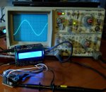
I haven't included the hardware interfacing code as this will be implementation specific - but, as is, the code runs in the simulator and you can compare the output with AD's online calculator at:
http://designtools.analog.com/dt/dds/ad9850.html
NB: the code assumes a 125Mhz crystal which seems to be the default. It would need modifying for another crystal frequency.
Its amazing what these little chips are capable of given a little ingenuity")
Hope this is useful
Peter
However, I found it was just about possible using a picaxe and a hacked version of Jeremy Leach's 32 bit routines.
The attached snippet calculates the 4 data bytes needed (the control word should be set to 0). These can be loaded via a parallel load or by a clocked serial load.
The code allows for frequencies from 1 to 99,990,000 Hz accurate to 1 in 10,000.
I haven't included the hardware interfacing code as this will be implementation specific - but, as is, the code runs in the simulator and you can compare the output with AD's online calculator at:
http://designtools.analog.com/dt/dds/ad9850.html
NB: the code assumes a 125Mhz crystal which seems to be the default. It would need modifying for another crystal frequency.
Its amazing what these little chips are capable of given a little ingenuity
Hope this is useful
Peter
Code:
#picaxe20x2
setfreq m64
#simspeed 0
'
' Calculates 32 bit data load for frequency on AD9850
' accurate to 0.01%
' 32-Bit (unsigned) maths on a PICAXE
' J.Leach 2006 , modified PM 26/10/2012
'
Symbol Procedure0StartAddress = 0
Eeprom 0,("+E*F*G/H=I")
'Word 0 (b0 and b1)
Symbol OperandLSW = w0
Symbol OperandLSWLSB = b0
Symbol OperandLSWMSB = b1
'Word 1 (b2 and b3)
Symbol T = w1
Symbol Temp2Word = w1
Symbol InstructionOperand = b2
'Word 2 (b4 and b5)
Symbol AccumulatorLSW = w2
Symbol AccumulatorLSWLSB = b4
Symbol AccumulatorLSWMSB = b5
'Word 3 (b6 and b7)
Symbol AccumulatorMSW = w3
'Word 4 (b8 and b9)
Symbol S = w4
Symbol Temp1Word = w4
'Word 5 (b10 and b11)
Symbol OperandMSW = w5
Symbol Address = b10
Symbol Address1 = b10
Symbol Address2 = b11
'Word 6 (b12 and b13)
Symbol InstructionCode = b12
Symbol Temp1Byte = b12
Symbol ProgramCounter = b13
Symbol Temp2Byte = b13
Symbol ErrorFlag = b13
Symbol Index = b13
'words 7-11
symbol E=w7
symbol F=w8
symbol G=w9
symbol H=w10
symbol I=w11
symbol Decade =w12
symbol byte0=0
symbol byte1=b4
symbol byte2=b5
symbol byte3=b6
symbol byte4=b7
symbol Crystalmult=10000
Symbol LCDOutPin = 6 'LCD used for alerting, but other methods can be used.
Symbol RTStartAddress = 80
Symbol RTEndAddress = 83
Symbol DenominatorLSBAddress = 84
Symbol DenominatorMSBAddress = 85
Symbol ErrorFlagAddress = 86
Symbol GPRStartAddress = 88
Symbol ProgramCounterAddress = 87
Symbol ERROR_Overflow = 0
Symbol ERROR_NegativeResult = 1
Symbol ERROR_DivideByZero = 2
Symbol RTStartLessb4Address = 76 '(80 - 4)
Symbol GPRStartAddressLessb0Address = 88 '(87 - 0)

Main:
Decade=100 'Multiply base frequency by this to get target frequency
'1, 10, 100, 1000, 10000 are valid values for the decade multiplier
E = 5000 ' base frequency set for 500Khz (5000 * 100)
'1-9999  are valid values for the base frequency
F = 42950 'approx 2^32/1000000
G = 8 'scale to use max precision for 125MHz crystal (1,000,000,000/125,000,000)
H = 10000/Decade 'scale the answer based on the decade selected
ProgramCounter = Procedure0StartAddress
Gosub ExecuteProcedure
'
'substitute serial or parallel chip load here based on hardware I/F selected
'
b0=byte4
gosub writehex
b0=byte3
gosub writehex
b0=byte2
gosub writehex
b0=byte1
gosub writehex
End

 '*************************************************
 '**** VIRTUAL ARITHMETIC AND LOGIC UNIT (ALU) ****
 '*************************************************

Add:

      Poke ErrorFlagAddress,ERROR_Overflow

      'Add LSW
      AccumulatorLSW = AccumulatorLSW + OperandLSW
      If AccumulatorLSW >= OperandLSW Then Add_1
      'Add Carry to MSW and jump to error routine if overflow
      AccumulatorMSW = AccumulatorMSW + 1
      If AccumulatorMSW = 0 Then CPU_Error

      'Add MSW
      Add_1:
      AccumulatorMSW = AccumulatorMSW + OperandMSW
      'Jump to error routine if overflow
      If AccumulatorMSW < OperandMSW Then CPU_Error
Return

Subtract:
      Poke ErrorFlagAddress,ERROR_NegativeResult

      'Subtract LSW
      Temp1Word = AccumulatorLSW
      AccumulatorLSW = AccumulatorLSW - OperandLSW

      If Temp1Word >= AccumulatorLSW Then Subtract_1
      'Borrow from MSW and jump to error routine if this will make the overall result
      'negative.
      If AccumulatorMSW = 0 Then CPU_Error
      AccumulatorMSW = AccumulatorMSW - 1

      'Note: No need to Subtract MSW as only OperandLSW is being used
      Subtract_1:
Goto Fetch

Multiply:

      Poke ErrorFlagAddress,ERROR_Overflow

      'Calculate the higher multiple and keep in Accumulator
      Temp1Word = AccumulatorLSW
      Temp2Word = AccumulatorMSW
      AccumulatorLSW = 0
      AccumulatorMSW = OperandLSW * Temp2Word
      Temp2Word = OperandLSW ** Temp2Word
      'Check for overflow
      If Temp2Word > 0 Then CPU_Error

      'Calculate the lower multiple and put in Operand
      OperandMSW = Temp1Word ** OperandLSW
      OperandLSW = Temp1Word * OperandLSW

      'Add the multiples to get the final result
      Gosub Add
Goto Fetch

Divide:
      Poke ErrorFlagAddress,ERROR_DivideByZero

      'Check for error
      If OperandLSW = 0 Then CPU_Error

      'Zero the Running Total
      For Address = RTStartAddress To RTEndAddress
            Poke Address,0
      Next

      'Calculate the quotient and remainder for 65535/OperandLSW
      S = 65535 / OperandLSW
      T = 65535 // OperandLSW

      'Store the denominator
      Poke DenominatorLSBAddress,OperandLSWLSB
      Poke DenominatorMSBAddress,OperandLSWMSB

      Divide_1:
      'Calculate S * AccumulatorMSW in the Operand, and add to Running Total.
      'Note: uses variables very carefully !
      OperandLSW = AccumulatorMSW
      Gosub SwapAccumulatorWithRT
      OperandMSW = S ** OperandLSW
      OperandLSW = S * OperandLSW
      Gosub Add
      'Update the running total
      Gosub SwapAccumulatorWithRT

      'Calculate the new Numerator
      OperandMSW = 0
      OperandLSW = AccumulatorLSW + AccumulatorMSW
      If OperandLSW > AccumulatorMSW Then Divide_2
      OperandMSW = 1
      Divide_2:
      AccumulatorLSW = AccumulatorMSW * T
      AccumulatorMSW = AccumulatorMSW ** T
      Gosub Add

      'Check to see if the new numerator is a single word. Loop back if it isn't
      If AccumulatorMSW > 0 Then Divide_1

      Temp1Word = AccumulatorLSW
      'Retrieve the running total
      Gosub SwapAccumulatorWithRT
      'Retrieve the denominator
      Peek DenominatorLSBAddress,OperandLSWLSB
      Peek DenominatorMSBAddress,OperandLSWMSB
      'Calculate AccumulatorLSW/Demominator and store in Operand
      OperandLSW = Temp1Word / OperandLSW
      OperandMSW = 0
      'and add to the Running total to give the final result
      Gosub Add
Goto Fetch

SwapAccumulatorWithRT:
      'Swaps the Accumulator value with the Running Total value
      For Address1 = RTStartAddress To RTEndAddress
            Address2 = Address1 - RTStartLessb4Address
            Peek Address1,Temp1Byte
            Peek Address2,Temp2Byte
            Poke Address1,Temp2Byte
            Poke Address2,Temp1Byte
      Next
Return

StoreAccumulatorLSW:

      Address = InstructionOperand - "E" * 2 +14
      Poke Address,AccumulatorLSWLSB
      Address = Address + 1
      Poke Address,AccumulatorLSWMSB
Return

CPU_Error:
      Peek ErrorFlagAddress,ErrorFlag
      Sertxd("ERROR: ",#ErrorFlag," ")
End

ExecuteProcedure:
      'ON ENTRY: ProgramCounter has been set to the start of the Procedure

      'Save the Program Counter
      Poke ProgramCounterAddress,ProgramCounter 'Save the ProgramCounter

      'Load General Purpose registers with corresponding E to I4 values
      For Address1 = 14 To 23
            Address2 = Address1 + GPRStartAddress -14
            Peek Address1,Temp1Byte
            Poke Address2,Temp1Byte
      Next

      'Set the Accumulator to 0
      AccumulatorMSW = 0
      AccumulatorLSW = 0

Fetch:
      'Fetch an Instruction code and operand from Program Memory
      Peek ProgramCounterAddress,ProgramCounter 'Retrieve the ProgramCounter
      Read ProgramCounter,InstructionCode
      ProgramCounter = ProgramCounter + 1
      Read ProgramCounter,InstructionOperand
      ProgramCounter = ProgramCounter + 1
      Poke ProgramCounterAddress,ProgramCounter 'Save the ProgramCounter

      'Load the contents of the specified Register into OperandLSW
      Address = InstructionOperand - "E" * 2 + GPRStartAddress
      Peek Address,OperandLSWLSB
      Address = Address + 1
      Peek Address,OperandLSWMSB
      OperandMSW = 0

Execute:
      'Execute the loaded Instruction

      Lookdown InstructionCode,("+","-","*","/","="),Index
      Branch Index,(Instruction_Add,Subtract,Multiply,Divide,StoreAccumulatorLSW)

Instruction_Add:
      Gosub Add
      Goto Fetch

writehex:
     b1=b0>>4
     gosub hexit
     sertxd (b1)
     b1=b0 & $0F
     gosub hexit
     sertxd (b1,cr,lf)
return

hexit:
     lookup b1,("0","1","2","3","4","5","6","7","8","9","A","B","C","D","E","F"),b1
return
Last edited: