ADC fluctuations

eclectic

Moderator
@ZOR
I'm using one of these:

http://nipponpulse.com/catalog/parts/search/motors-rotary-tin-can-steppers/part_id:218
('Cos I've got one in the toybox :)

Wiring and sequencing follows both M.3, p. 15 and, in parallel,

http://nipponpulse.com/catalog/document/4b16d0783ef33_PF(C)_Unipolar_Wiring.pdf

AXE117 / 14M2

"My" code (derived from the Forum) works.

I simply added a 10k potentiometer (C.4 , gnd, v+).

Then I loaded the code provided by Goeytex.
That worked as well. :)

You're spoilt for choice mate! :)
e
 

ZOR

Senior Member

eclectic

Moderator
@ZOR

I'm getting a bit lost now.
So, for me and any newcomers,

Could you wind back and tell us:

1. What is your overall project?

2. What have you built so far?

3. What works?

4. What doesn't?

5. What next?

e
 

Goeytex

Senior Member
The corrected code should solve the jumping.. and for testing you may need to add to rather than subtract from the "rest" value. During the "Rest" pause is actually when current is flows to the coil(s) . If this time is too short then there may not not be enough current to move the rotor before the next coil is energized.

Your motor is has a 5.625 /64 step angle and is designed to run very slow. It will take ~ 4096 steps to turn one shaft revolution. If one step takes ~3ms then the RPM at the output shaft should be about 4.88 RPM
 

ZOR

Senior Member
Thnkyou Goeytex, I will try it again.

Re Project:
Having had a burglary 2 years ago, I have been on a project of fitting security cameras on and around the house.
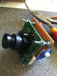
BOARDCAM.jpg
I am using the cases of garden floodlights to house motorised pc board cameras. I have been using servo motors to pan and tilt these camera boards.
Now I am trying to learn about and use stepper motors.
I have had a few problems of recent times with servo's having jitter, Hippy recently helped me sort out a problem I was having.

So I thought I would give steppers a try now, having bought some very cheap motors that seem to be very well made.
First problems were I did not know how to drive them. Eclectic gave me some code, and after just changing my motor connections proved to work very well.

I then tried using a potentiometer to make my stepper go forward and back. I was using a variable to log the last pot (ADC value) to know if the pot had been altered, however the ADC value kept bouncing between its value by 1. This then caused problems as it falsely told my motor that I had turned the pot. I then tried scaling, which did seem to clean up my ADC values, however I then sarted to see I was not getting a full 180 degree movement on the motor unless I had large loop values each time to move the motor round. This then led to me feeling I was not getting full control between me and the motor, as well as still not getting full 180 degree rotation.

So my drive circuits works, no problem.
I have dropped the potentiometer for now (ordered some encoder controls for future trial)
Adopting direction buttons (hold button down, motor moves, release, motor stops)
Looking at using IR remoting camera (IR TX at end of wire) (tube in camera with TX and RX), cameras are powered at location.

So really it's all areas, and greatful to this Forum for expertise help.
 
Last edited:

ZOR

Senior Member
I just tried the code again.

The motor still barely turns?

The only way I can get a rotational speed to match eclectic's code is by reducing my pause from 2000 to 50?

What is the purpose of the counter loop? If I remove it, things are the same. If I leave the pot at one end the motor goes round and round.

I wondered why the "motor off" code where it is, is it in the right part of IF then statement. Thought it would have been related to where the pot was. I remmed out both lines and the servo still stops midway on the pot, although maybe still powered, don't know.

So it's a mystery why I am getting these results.

Thanks
 

Goeytex

Senior Member
The code was based upon a motor I have here that turns at close to 350 RPM so it is not surprising that the pause needs to be reduced and was intended to only rotate CCW or CW or stop based upon pot position. Your initial specification did not say that shaft position should be proportional to pot position or that you were wanting to replace servos with stepper motors.

It is important to be very clear and specific when describing a project or asking for help. Had you initially provided a clear and precise specification, along with other important details such as what Picaxe Chip, motor specs, and what the project actually was ...I could probably have done a more appropriate code example. I thought you were simply testing a motor for fun.
 

ZOR

Senior Member
Thankyou Goeytex, sorry I do understand some things. However my posting was originally about ADC noise, and prior to your input I had made the comment "However I now find I cannot achieve 180 degrees control/movement from the pot" based on the pot making the motor go back and forth.

Never mind, I appreciated your inputs.
Can I just ask back on the question of what the loop does in your circuit, and the switch off statements are at the end of loops.

Thanks again
 

Goeytex

Senior Member
The loop simply sends a fixed number of pulses to the motor. To turn your motor 180 degrees that would be about 2048 steps. Since there are 4 pulses (steps) per iteration... for 180 degrees that would be: "for counter = 1 to 512. The motor off allows a visible indication of where the shaft stops to confirm/ verify operation & code. I turned the motor off (PinsD = %00000) instead of holding with two coils energized ( PinsD = %01010) and drawing max current continuously during the pause to prevent the motor from heating up too much. If the pot is still off center position after the pause, the process will repeat and the motor turn another 180 degrees in the same direction (assuming 512 loop iterations).

It would be easy enough to have code move the motor to a position based upon pot position.
 

ZOR

Senior Member
Many thanks, now I understand. It does seem very smooth running from the pot, I have not see any twitches/jitter while it's been running, unlike my earlier personal attempt. I will try and make it follow where the pot is set, ulike at present going in one or the other direction after the pots half way position. It is a nice feature having it stop in the central pot position. Thanks, I will carry on with it. Have a good weekend when it arrives
 

Goeytex

Senior Member
Since I had some time on my hands I continued on with the code, making the motor shaft follow the pot position over 180 degrees. No encoder.
I put a switch on the shaft wheel. At power up the motor is turned until the switch is activated to establish a relative position, Then moves x
number if steps to establish "Center" and is given a position of "12".

My motor has 48 steps per revolution so for 180 degree I am using position 0 - 25 with 12 being center. The code keep track of position by incrementing or decrementing a position variable after each step.

Then ADC was scaled to be 0 to 25 full scale. Turn the pot and the shaft wheel goes to the position determined by ADC. This works very well as long as the motor does not bind and lose track of position (It hasn't yet).

The main issue is heat. Since there is constant current to the motor when it is stopped (holding a position) it gets very hot. I will probably add a little routine so that if ADC does not change for more than 200ms current is turned off.
 

ZOR

Senior Member
Hello Goeytex, thats interesting. I started a new thread (stepper motor limits) where I was looking at ideas for limiting the travel on my two pan/tilt motors. I was going to try and fit IR slotted interrupt devices on in preference to micro switches etc. Yours is something I was thinking of doing for power up mode, where the motor gets driven to it's known limit at on end, then it knows where it is. If after a while it drops it's count I can turn it off and make it learn again.
Maybe I should have kept the thread here, but I thought it to be a different subject. Never mind, will wait for the kicking if applicable.
 

ZOR

Senior Member
Re message #38

I have just received a mechanical rotary encoder, as suggested as an alternative to a pot for ADC input.

Looks very nice, never used an encoder before, can someone enlighten me how I use it. Thanks
 

MartinM57

Moderator
Interesting - I'm sat here with my first ever rotary encoder that arrived today in the post - although I'm not intending to use it on a PICAXE. It's a fancy one with RGB LEDs in the transparent shaft, plus a push switch :)

http://www.picaxeforum.co.uk/showthread.php?20710-Controlling-and-application-with-both-IR-and-a-rotary-encoder&p=198520#post198520
...might help. It seems fairly advanced stuff to me..you might have to have quite a cute program design to do whatever your main program is doing and still be able to respond to someone whizzing the encoder around randomly at high speed. Reading a pot with ADC is far, far easier....

Searching for "rotary encoder" (with the quotes) will dig up a few more threads no doubt
 

hippy

Ex-Staff (retired)
Re message #38

I have just received a mechanical rotary encoder, as suggested as an alternative to a pot for ADC input.

Looks very nice, never used an encoder before, can someone enlighten me how I use it. Thanks
First thing is to find a datasheet and confirm it's as the datasheet claims. Google's your friend and this is perhaps a good start -

http://www.bsom.org/?p=43
 

ZOR

Senior Member
Thanks again. I don't have any datasheet with the device, putting a meter on the 3 terminals seemed dead so I guess I put volts on the outer 2 ags. The other 2 being a switch.

I will have a play later, thanks for the link.

I think Martin seems very smug with his LED's in the transparent shaft!!
Regards
 

boriz

Senior Member
If the encoder is like mine, and it looks like it is, this code should work:

Code:
do
	do
		b1=b0
		b0=pins & %11
	loop until b0<>b1
	b1=b1&%10/2^b0&%1
	if b1=1 then
		'encoder rotated one click clockwise
	else
		'encoder rotated one click anti-clockwise
	endif
loop
On the three pin encoder, one pin goes to +5v and the other two go to Picaxe inputs 0 and 1 with pulldown resistors (anything from 1k to 10k should be ok).
 

MartinM57

Moderator
YAPER (Yet Another PICAXE Encoder Reader)

This seems to work well and is relatively simple - uses an interrupt so that the main loop isn't tied up waiting for the encoder to move

Seems solid to whizzing the encoder round as fast as possible by hand and also dallying slowly between detent positions

Using the xxx_COUNT values in your main loop is an exercise for the reader..

Code:
#picaxe 14m2
#no_data
#terminal 38400
setfreq m32

symbol false	= 0
symbol true	= 1

symbol intHappened = bit0

symbol LEFT_COUNT = w5
symbol RIGHT_COUNT = w6
symbol PUSH_LEFT_COUNT = w7
symbol PUSH_RIGHT_COUNT = w8

'hardware...
'PIXAXE 14M2
'encoder with switch and RGB LEDs...http://proto-pic.co.uk/rotary-encoder-illuminated-rgb/
'datasheet...http://dlnmh9ip6v2uc.cloudfront.net/datasheets/Components/Switches/EC12PLRGBSDVBF-D-25K-24-24C-6108-6H.pdf

'wiring...
'encoder push switch pin 3 to pinC.0 (leg 7), tied low with 4K7
'encoder push switch/LED common pin 5 to +V
'encoder channel A switch to pinC.1 (leg 6), tied high with 4K7, with 33nF cap between leg 6 and ground (for debounce/spike suppression)
'encoder channel B switch to pinC.2 (leg 5), tied high with 4K7, with 33nF cap between leg 5 and ground (for debounce/spike suppression)
'encoder channel switch common to ground
'encoder RGB LEDs (pins 1, 2, and 4) can be switched on (or PWM'ed) by connecting to separate PICAXE output pins via separate 470R and setting the pins low

 	pause 250

	'interrupt on channel A low
	setint %00000000, %00000010, C

	do
		'if there was an interrupt print the counters
		if intHappened = true then
			'separate sertxd's - if they are all in one, interrupt is delayed too long (sometimes)
			sertxd (#PUSH_LEFT_COUNT, CR, LF)
			sertxd (#PUSH_RIGHT_COUNT, CR, LF)
			sertxd (#LEFT_COUNT , CR, LF)
			sertxd (#RIGHT_COUNT, CR, LF, CR, LF)
			intHappened = false
		endif
	loop

interrupt:

	'show main loop that an interrupt happened
	intHappened = true
		
	'if channel B is low, we are going right
	if pinC.2 = 0 then
		'increment count depending if switch is also pressed
		if pinC.0 = 1 then
			inc PUSH_RIGHT_COUNT 
		else
			inc RIGHT_COUNT
		end if
	else 'we are going left
		'increment count depending if switch is also pressed
		if pinC.0 = 1 then
			inc PUSH_LEFT_COUNT 
		else
			inc LEFT_COUNT
		end if
	end if
	
	'wait for Channel A to go high again - shouldn't take long (famous last words)
	do   
	loop while pinC.1 = 0

	
	'set interrupt again
	setint %00000000, %00000010, C
	return
 
Top