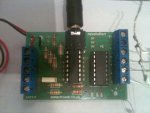
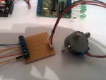
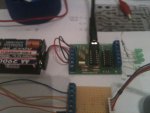
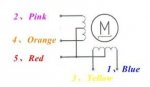
The AXE-17 pcb is populated using all the parts supplied. It has battery connection. The motor is mounted off the board, and is powered with 5 volts from a PSU (in case higher current wanted) and the 0v ground is commoned up to the AXE-117 ground.
I replaced the ULN2003A and it cured the programming problem just once, the next time it failed, and would only get programmed if I removed the PSU supply. So maybe another ULN chip has gone.
I'm not going to waste any more time soon, I was going to do all this with a 555 and decade counter. This should have been easy by all accounts but is now becomming a pain.
Why on the AXE-117 board is there no pad connection to Pins 1 and 16?
Why is there not a jumper between the serial output and Pin 2 of the ULN chip.
Okay it's project board, but could have been better for the price.
I just hope coming over to this thread I don't lose continuity of the Stepper motor
Thanks