Solved - Read DHT Temperature/Humidity from 32MHz PICAXE

pleitch

New Member
Hi all.

The full program and documentation is available here:
http://www.prlsoftware.com/dht-for-32-mhz-picaxe.aspx

This article is about programming the PICAXE to receive data from the DHT sensor series at 32MHz. Just a bit of background first though.

I've just started developing PICAXE development so each time I work on an aspect of PICAXE I'm coming to it fresh, with little knowledge of electronics and no knowledge of ICs and microcontrollers. So if you see an better way of doing what I've outlined, please reply. For instance, I've used 2x 555 timers but I'd never heard of a 555 before so I don't know if there is some type of combined multi-555 IC or perhaps some other IC that does what I've done with 2 x 555 timers.

Back to the DHT...

There are other posts on the DHT, many of which mentioned a 555 timer. I tried it on my 18M2+ at 32 MHz and it failed to read all of the bits - but did read a lot of them. However, the approach got me interested in the 555 so I read some more. I came up with a 2x555 solution that, along with some mathematics, allows 32MHz PICAXE to read the DHT family of processors.

NOTE - I tried lower speeds, such as 16MHz but it didn't work, however 20MHz was not tested and may work.

In short the "down time" of the DHT range is 50us. That's far too short for any PICAXE to process what it needs to process (put a PulsIn value into a variable and then re-issue the PulsIn). The 555 timer approach I found on this forum altered this to be a 60us down time (processing time) at the expense of the "up time" of the zero and one bit. This approach works for 64MHz PICAXEs AND I would reccomend that this approach (or variants listed in the forum) still be used for 64MHz processors as this approach is simpler to construct and has smaller program code.

However, the 60us down time is still too short for 32MHz PICAXEs. I've implemented an approach that increases the available processing time to 110us, which is more than double the original 50us timeframe and more than enough for 32MHz processor.

This has been done at the expense of zero bits. Instead of reading in every zero bit I ONLY read one bits and the zero bits are then calculated from the time gap between 1 bits. Therefore the program is necesarily longer due to the reconstruction required (the current program is 512 lines in length to do the read).

The specific theory and mathematics are all on my web site (link above).

The program has only been tested on DHT11 units. I'll be purchasing DHT22 unit and making adjustments to the program when they arrive.
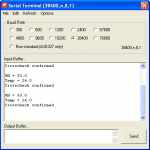
SerialOut.PNG
 

g6ejd

Senior Member
This is an interesting problem to solve and your solution is equally so.

If the DHT has a 40-bit word output and word length in time is 4ms, that's a bit time of 100uS.

BTW It would be really useful if the PICAXE allowed a call to some machine code routines like CALL &nnnn with no checks and no warranty, then some CPU level code could solve this easily, writing the result back to a memory location, returning to the PICAXE Basic then reading the result.

As you have found the 18M+2 nearly worked, then compiling the code (Free compiler available from PICAXE website) should solve the problem even at lower CPU speeds and probably give you sufficient time budget to do more.

The PICAXE is not really the tool for this task, that said, when compiled I'm sure it is.

I believe your shiftin routines could be shorter/optimised thereby giving you much more of a time budget using the indirection pointers (@BPRT) like your already doing.
 

pleitch

New Member
Thanks. I'll source one of those 556 chips.

Can anyone please confirm that the compiled code is smaller and faster than deploying with the standard program editor? I thought the program editor did compile and deploy to the device, that the command line version simply provided a cut-down process of doing the same thing.

In the mean time I'll hook the existing circuit up to an LCD, take some photos and post as a completed project.
 

hippy

Technical Support
Staff member
Can anyone please confirm that the compiled code is smaller and faster than deploying with the standard program editor? I thought the program editor did compile and deploy to the device, that the command line version simply provided a cut-down process of doing the same thing.
The code generated by the command line compilers and the Programming Editor will be the same; same size, same execution speed.

What was meant was; if it could have been written for a PICAXE which supported compiled native code the equivalent program - rather than being interpreted - it would have been smaller and faster.

That's true and, as said, the PICAXE wasn't designed for handling high speed signalling. It doesn't make the PICAXE a failure though; in the same sense that the family car isn't a failure because it cannot achieve speeds a dragster would. You just have to resort to some tricks if you want a family car to compete, in the same ways tricks are used here to allow the PICAXE to do what is otherwise awkward for it.

On which; it's a very good solution to the problem and I haven't been able to think of an alternative for an M2 which would better it.
 

g6ejd

Senior Member
AFAIK PICAXE Basic uses a token based psuedo code, which is then interpreted line-by-line. As to code size of the two (P-Code + PICAXE On-Chip Interpreter) and (Native compiled code) it depends on the complier, as many include the whole of a library for say I/O when just one part of it is used, an example of this is the Arduino, that compiles a short FOR NEXT style programme to about 8K, when I estimate in native code terms should be no more than say 256bytes!

Why not try the compiler and see what the image size is, you could always delete it afterwards if it proves to be too big. I presume you would need a blank/bare PIC to utilise it or have to over-write the PICAXE code.

[Clearly the PICAXE compiler is interesting:)]
 

techElder

Well-known member
g6ejd, what is this "compiler" you speak of for the PICAXE? You keep referring to it, but are not being specific. Hippy already said that we have what we have with the PICAXE as is.
 

g6ejd

Senior Member
http://www.picaxe.com/Software/Drivers/PICAXE-Compilers/

I have to admit I have never really read the documentation - after all I am an Engineer :) but I have now and see they take the PICAXE Basic text file and produce the same P-Code that the PICAXE Programme editor would do/does, for onward download to a PICAXE, they are more for cross-platform programming of a PICAXE, where you can't run the Programme Editor. Not strictly a compiler, more of a multi-platform development environment.

There are more than a few true compilers for PIC chips around that take BASIC and produce native CPU code, but none will compare with the flexibliity of the PICAXE solution which remains my favourite; the Arduino nearly swung me, but failed on code size and the lack of I/O support, yes I can add my own libraries for I/O, but life's too short, so I spend my virtual life here in this forum rather than Arduino land :)
 
Last edited:

Goeytex

Senior Member
These are the same compilers used with the Program Editor. There is no performance gain by using these.
 

hippy

Technical Support
Staff member
@ pleitch : One thing I do find confusing on your web site are your timing diagrams. If you could get used to spreading each trace over two lines, using underscore and vertical bar, you will probably find those are much easier to understand. Some people prefer graphic timing diagrams but I don't think ASCII is a problem if it's clear where the edges are ...

Code:
           |<---- 1 ----->|<-- 0 -->|<-- 0 -->|<---- 1 ----->|
       ____        _______        __        __        _______
DHT        |______|       |______|  |______|  |______|       |___
           :  50  :  70   :  50   27   50   27   50  :  70   :
           :      :       :                          :       :
           :      :--->:  :                          :--->:  :
           :           :  :                               :  :
         __:           :__:                               :__:
555 A  _|  |___________|  |_______________________________|  |___
        :10     110    :10              264               :10
        :              :                                  :
        :              :                                  :
        :___________   :____________                      :____________ 
555 B  _|           |__|            |_____________________|            |_
             110     10     110               174              110
 

Goeytex

Senior Member
And on a minor note: The blocking diode is not connected in the Pebble diagram. It needs a couple of jumper wires.

Nice work.
 

mrburnette

Senior Member
<...> the Arduino nearly swung me, but failed on code size and the lack of I/O support, yes I can add my own libraries for I/O, but life's too short, so I spend my virtual life here in this forum rather than Arduino land :)
Apples & Oranges... An "apple-apple" approach would require you to take the full size of the PICAXE firmware + user code after compile and compare that sum against the output of the avr-gcc HEX code + 2K ... The boot loader is 2 K for the -duo and should be included in the comparison.
code-size-comparisons-just-for-fun

The PICAXE token process 'appears' to be efficient - maybe too much so since a lots of uC cycles are spent uncompressing data... once required due to limited flash, but with the PICAXE chips today, flash is not as critical.

- Ray
 
Last edited:

pleitch

New Member
Thanks.

I'm new to PICAXE and it's been over 10 years since I last did Data Comms, and even then never at such a raw/low level.

I'm working on another project right now but when I'm done I'll come back and make the ammendments you've suggested.
 

ybarrap

New Member
I've just completed this project with an 08M2 32MHz using Philip Leitch's code. Thanks to Maguin Michel, Goeytex and Philip Leitch for the progressive advancement of utilizing the DHT11 sensor with the PICAXE. The biggest challenge I encountered was to determine how to trigger from low to high rather than the usual high to low part of the 555 cycle. I finally figured out that Phlip used an PNP BJT on Pin 6/7 which solved the problem. Minimal testing shows that the DHT11 was accurate enough but could take over 10 minutes to settle in on the correct temperature. Again, Philip, your documentation was so wonderful and easy to follow. I was hesitant about mentioning the BJT, because the learning experience of figuring this part out has lots of value; however, I decided to do so because otherwise your solution may not be fully appreciated if a user was unable to repeat. This is a rather old thread, but I hope that you will find this eventually and accept my gratitude for the time you took to develop and document this solution. It was a real pleasure working on this project. Goeytex, your documentation was very helpful as well and helped me understand what Philip did as well as on how to communicate on the single-wire using two PICAXE ports. Of course, Maguin Michel, your creative approach with the single 555 started the whole thing. Again, thank you all.
 
Top