Jeremy Harris
Senior Member
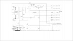
I wanted to build a small, light, combined battery pack and power display for a new folding electric bike I'm building, and though I'd see just how much functionality I could get from a budget 16 x 2 line OLED. The 18M2 used on these nice little displays has four spare pins available, c.0, c.1, c.2 and c.5. I needed to be able to measure current (up to 20 or 30 A), voltage (up to 50V), detect when a button was pressed and control a high power switch to run the bike battery on and off. I also wanted to have a circuit that, when turned off, had zero drain from the battery, not even 1µA.
After much experimentation I managed to get the OLED display (an AXE133Y) to drive everything, and give me a nice bar graph "fuel gauge" display of remaining battery capacity. I needed to make a circuit board to carry the big FET power switches and the additional circuitry to control them, plus a Hall effect current sensor and a 5 V regulator to power the Picaxe.
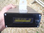
The box will mount vertically on the handlebar stem, with the display and on/off button on the top. The string loop is connected to a magnet that operates a reed switch; when pulled out it disables the on/off button. The Picaxe can "commit suicide" by turning off its own power supply, either if the button is pressed or if it detects that no current has been drawn for a couple of minutes. Doing this makes sure that the bike can't accidentally be left turned on, draining the battery.
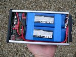
Here are some photos of the semi-finished box, if anyone is interested I can post the schematic and code later. There is a commercial brushless motor controller board under the power switch board, so this box is all that's needed to run the bike and display information on power use and remaining battery capacity.
Front view, showing the lithium batteries for the bike, the interface board with the power switch and sensor to the left and the rear of the OLED display:
Top view, showing display:
After much experimentation I managed to get the OLED display (an AXE133Y) to drive everything, and give me a nice bar graph "fuel gauge" display of remaining battery capacity. I needed to make a circuit board to carry the big FET power switches and the additional circuitry to control them, plus a Hall effect current sensor and a 5 V regulator to power the Picaxe.
The box will mount vertically on the handlebar stem, with the display and on/off button on the top. The string loop is connected to a magnet that operates a reed switch; when pulled out it disables the on/off button. The Picaxe can "commit suicide" by turning off its own power supply, either if the button is pressed or if it detects that no current has been drawn for a couple of minutes. Doing this makes sure that the bike can't accidentally be left turned on, draining the battery.
Here are some photos of the semi-finished box, if anyone is interested I can post the schematic and code later. There is a commercial brushless motor controller board under the power switch board, so this box is all that's needed to run the bike and display information on power use and remaining battery capacity.
Front view, showing the lithium batteries for the bike, the interface board with the power switch and sensor to the left and the rear of the OLED display:
Top view, showing display: