PICAXE in Space

srnet

Senior Member
I would imagine that by now your transmitter options are pretty much frozen
Yep, slow FM Morse beacon, some fast FM Morse data (battery and Solar voltages and current) and a fast FM Morse data packet which is 20 bytes or so of system data. Then the same 20 bytes transmitted as a FSK data packet. With a 10 second listen period for an uplink command packet (TX on or off) this sequence repeats approx every 40 secs.

Receiver for the Morse is any UHF receiver, cheap ones will do, with addition of a yagi, and possibly a LNA.

The ground station for receiving data telemetry and transmitting uplink commands, is a PICAXE 28X2\RFM22\RFM23BP PCB costing around £20 to build with the addition of a yagi and possibly LNA. For the uplink and depending how far out you need to go, a UHF linear is required, 30W should allow for command link all the way out to the radio horizon. For a close pass, the linear is likely not required.

Whether someone can come up with code for a software defined radio (or similar) to decode the FSK data from the Hope RFM, we dont yet know.

As far as is possible this project from the outset has been intended to be a DIY project for Schools and Colleges (hence the use of PICAXE), no fancy HAM gear required at all. If you can use a £20 receiver you have built yourself, a £10 LNA and a yagi made from sticks and wire to get real data from space, then why not ?
 

Paix

Senior Member
a UHF linear is required, 30W should allow for command link all the way out to the radio horizon.
no fancy HAM gear required at all.
OK, I'm kidding,

but THE ground station might benefit from some smart backup. After all, the name of your game has to be guaranteed communication, as far as possible. Great to do with the budget ground station and demonstrate that it can be done effectively without any expensive equipment and making your own antenna is a great place to make major savings.

I think that an amateur radio communications receiver should be a drop in plan "B" option for the system, given that there are possibly a few unknowns.

Have you had a chance to copy any other birds with your proposed setup? To the point of recording the signals if not being able to decode them effectively.

I guess that you will be using an Amateur Radio transceiver when in command mode and I assume that the ground station transmitter will be offsetting for the inevitable doppler? There was a fair bit done with handheld radios and yagis, but I imagine that they stretched the hand eye ear coordination a little and I don't know quite how the doppler was taken care of in those situations.
 

boriz

Senior Member
Forgive me if this has already been covered. Since your satellite can receive shut-down commands, can't it also receive other instructions like 'send data now', or even 'send the basic slow CW data now' and 'send the denser more complete fast data now' type interrogation signals? Wouldn't that save a whole lot of power?
 

srnet

Senior Member
Forgive me if this has already been covered. Since your satellite can receive shut-down commands, can't it also receive other instructions like 'send data now', or even 'send the basic slow CW data now' and 'send the denser more complete fast data now' type interrogation signals? Wouldn't that save a whole lot of power?
It could, but I choose to keep the software as simple as possible, for this first mission.

The current software fulfills the basic objectives, power management, slow Morse beacon for humans, fast Morse data and command uplink.

There is a test packet, which if received, will result in the incoming RSSI being transmitted as slow Morse.
 

Graham O

Member
For the receiving ground stations, rather than control station, a better receiver to a UHF handheld would be one of the RTL-SDR TV tuner sticks. On their own they are cheap, about £15 and even with a preamp, the cost would not be much more than the handheld and would alleviate a lot of the problems. If it's a cheap handheld, then it may only tune in 5KHz steps, so it is possible to miss the data as it is outside the passband and if a quick packet, it could be missed before being captured. A TV tuner stick could be set to a 20KHz bandwidth so it would receive all the signals and doppler would not be a problem to signal capture. Is the slow morse beacon on the same frequency as the fast morse data? If not, listeners will have trouble knowing where to receive as there is no signal with morse until the data is sent. Perhaps 10s of carrier before the data would help listeners tune in and be ready.

Do you have any error checking on the data packet? A checksum at the end would give you confidence that the data received was what was sent.
 

Graham O

Member
But your listeners with UHF handhelds won't have that facility. And is the intention that there will be listerners all over the world?
 

Graham O

Member
Error checking. If you are using a RFM22 tx/rx at both ends for the ground station, that will have error checking, but listeners using a cheap handheld won't. Unless you are going to build it into the decoding software.
 

srnet

Senior Member
Error checking. If you are using a RFM22 tx/rx at both ends for the ground station, that will have error checking, but listeners using a cheap handheld won't. Unless you are going to build it into the decoding software.
If your question relates to the fast Morse data packet, then that does have a check digit on the end.
 

Paix

Senior Member
How will your RFM22 groundstation receiver be expected to track the doppler, given that the signal is likely to be better than 6kHz low at AOS and 6khz high at LOS?

As Graham has said, with a USB DVB-T stick used as a SDR receiver, receive bandwidth is not likely to be a problem and the effects of doppler can be readily seen.
I bought one of these on eBay a little while ago and the guy selling was a G7, more than happy to me help get it hackling with some of the available SDR software. Alas, it's still sat in it's box due to lack of time.

Anyone outwith the official ground station team and with experience, would probably be tracking your bird using a sideband receiver on USB/LSB rather than FM.and continuous tuning rather than stepped channels is pretty much a given.

As was pointed out, the space segment is pretty much frozen, but that doesn't mean that the ground station segment isn't still a work in progress, beyond the official ground control station, where again most if not all the decisions have been made already. The residual audience of, presumably, radio amateur operators who have an interest in such things and schools if they are lucky enough to be sufficiently informed to take part. So the ducks need to be lined up for schools. Informed early, be in a position to develop or loan the appropriate technology and have it running before the satellite re-enters the atmosphere.

Edit - of course, the transmission isn't FM. My error.
 

srnet

Senior Member
How will your RFM22 ground station receiver be expected to track the Doppler, given that the signal is likely to be better than 6kHz low at AOS and 6khz high at LOS?
The RFM22 does this automatically, assuming you enable the AFC.
 

srnet

Senior Member
437.505Mhz.

For the data telemetry, one of the ground station PCBs in the lost model locator project I published is being used, together with a LNA and a yagi and a 30W linear for uplink. I have tried an SSB SP7000 LNA and that works well, but hardly a cheap device so I am continuing to experiment with cheaper LNAs (which are normally wideband devices) and bandpass filters. Received data will log to PICAXE serial terminal or PC file on an OPENLOG logger in CSV format. Software for the ground station, and satellite, to be published once its shipped from the US to Italy. After that its assembled into the launcher, then shipped to somewhere in Russia for launch from a missile silo.
 

srnet

Senior Member
For a simple and cheap preamp I can recommend the G0MRF one at http://www.g0mrf.com/432LNA.htm. Works well and easy to construct.
Easy enough to make yes and a well presented kit.

However it is a wideband device by design, and in practice it only yields 3dBm or so of gain, so it needs to be tested with some bandpass filters to see if the wideband 'noise' is affecting the RFM22 RF front end. Some time needs to be spent with a spectrum analyzer to see what is going on, which I dont have time for at the moment.
 

Paix

Senior Member
The SSB SP7000 LNA is good for around 20dB of gain at an eye watering £260. Is it worth waving your "space card" at the likes of Waters and Stanton for a even a loan unit. Space is always good publicity and although the boss will tell you that times are hard, they might have one that they use for demonstrattion purposes in the shop. Worst case scenario is, "NO"

The ATF54143 also claims 20dB gain, but would require a lot more work to be ready to stick up the pole and so not particularly attractive, but losing around 17dB sounds a bit much if it only realises around 3dB in actual practice.

OK on the RFM AFC. Will it pick up a signal coming in 6kHz or so low of the designated frequency or will the receiver have to meet the signal and then track until LOS?
 

srnet

Senior Member
The ATF54143 also claims 20dB gain, but would require a lot more work to be ready to stick up the pole and so not particularly attractive, but losing around 17dB sounds a bit much if it only realises around 3dB in actual practice
I would be concentrating on getting it working on the bench, hopefully with more than 3dB gain, before worrying about a masthead mount. I had that LNA in one of those 2 part alluminium boxes complete with batteries, charge socket and switch. Think it needs to be in a better, say diecast alluminium box, with only a power socket and a screen between the in\out sides. And then maybe some bandpass filters.

OK on the RFM AFC. Will it pick up a signal coming in 6kHz or so low of the designated frequency or will the receiver have to meet the signal and then track until LOS?
With TX and RX frequencies deliberately offset, there is no noticeable performance degradation up to 10khz, and only a couple of dBm maybe at 15khz. Which is good for more normal uses of the RFM22 as the crystal used is not of the highest tolerance, although it is fairly temperature stable.
 

Graham O

Member
However it is a wideband device by design, and in practice it only yields 3dBm or so of gain,
I'm puzzled. I'm getting about 15 to 20dB of gain at 435MHz, although I have no way of measuring noise. Are you saying that the broad band input is desensitising the RFM22? Are you sure there isn't a better receiver you can use?
 

srnet

Senior Member
Are you saying that the broad band input is desensitising the RFM22?
No.

"However it is a wideband device by design, and in practice it only yields 3dBm or so of gain, so it needs to be tested with some bandpass filters to see if the wideband 'noise' is affecting the RFM22 RF front end. Some time needs to be spent with a spectrum analyzer to see what is going on, which I dont have time for at the moment.

So I dont know ..... yet.

Are you sure there isn't a better receiver you can use?
There might be, but I never found one.

Besides, the receiver code for the satellite RFM22 is the same as for the ground station RFM22, which makes for simple coding.
 

Graham O

Member
Rather than worry about a spectrum analyser and filters, try the preamp on another radio and that will tell you if it's the preamp or the RFM22. dB not dBm for gain by the way.

How much of the transmission protocol code are you using? Are you handshaking between the ground and satellite, i.e. send packet, get back acknoweldgement, send next packet etc?

If you are not handshaking, then I would suggest that even a few hundred lines of code is easier than trying to build a filtered preamp and probably cheaper than a commercial one.
 

srnet

Senior Member
If you are not handshaking, then I would suggest that even a few hundred lines of code is easier than trying to build a filtered preamp and probably cheaper than a commercial one.
A few hundred lines of code on\with what though ?
 

Paix

Senior Member
I take your point about requiring bandpass filters, probably a problem with the lack of a proper front end on the receiver.

A good few years ago my "station" comprised a hand held FM transceiver (2m), a 30W linear amplifier and a succession of antenna. I improved the station no end by elevating the antenna and being on a RAFARS net at the time, the members were well spread geographically. Each five foot section of pole under the colinear antenna gave a noticeable improvement in received signal and the reports that I was receiving was commensurate. Then one day I popped in another length of pole and the receiver started receiving signals that didn't appear to be anywhere nearby. The receiver had run into blocking as the mixer was overloaded due to the lack of front end selectivity - what front end in fact? That was about the time that I became interested in brick wall band pass filters, but I upgraded my transceiver instead and the moment passed.

As you have indicated, a LNA also amplify the noise and other nearby junk, including repeaters, and can end up much where I was. It's like going up a mountain thinking that the height will give you a much better range. It also brings in a lot more signals that weren't originally of any consequence, having been filtered out already by mother earth. Just another insight which may or may not be of any relevance. Possibly why I harp on about a comms receiver as plan B in the background! A symptom of previously burned fingers here :)
 

srnet

Senior Member
I take your point about requiring bandpass filters, probably a problem with the lack of a proper front end on the receiver.
Absolutely.

Possibly why I harp on about a comms receiver as plan B in the background! A symptom of previously burned fingers here :)
Sure, and as I have previously mentioned, someone will be looking at this, but its not entirely certain that the SDR approach will work, so I dont intend to dump plan A.
 

srnet

Senior Member
I eventually had a chance to implement and test FSK RTTY from the RFM22 and the reception of it on a number of radios, including the cheap (£6) DVB TV Dongles.

The baseline is the RFM22 data packets (100mW) where the LOS range has been tested at 40kM, with 1/4 wave antennas.

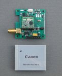
The PICAXE satellite ($50SAT) has several different modes of transmitting, a slow Morse beacon, fast 120WPW Morse data, recently added AFSK RTTY and FSK RTTY plus of course the RFM22 data packets themselves.

I programmed a PICAXE $50SAT PCB to transmit a message with each of the modes. Then repeat the modes in a cycle with power reducing from 20dBm to 1dBm in 8 steps. The transmitter was put on a hillside outside of Cardiff at a distance of approx 4kM from my shed. The message being sent was the "QuickBrownFoxJumps". PC decode software was FLDIGI.

The mast with the receiving antenna was adjusted in height so that the RFM22 data packets were received only at 20dBm, power level 7 and were not received at power level 6, 17dBm.

The radios I had to test were from very cheap, £6, to not cheap;

Yaesu FT817 transceiver, £550
Yaesu FT60 HT transceiver, £150
UV100\VX3R HT Transceiver, £25
Funcube Dongle Pro +, SDR# PC Software, £150
DVB RTL2832 TV USB Dongle, SDR# PC Software, £6
$50SAT Ground station PCB, £20

These receivers were tested from the comfort of my shed to see at what power level the reception failed. The FT817 and Funcube Dongle received the FSK RTTY reliably at minimum power from the RFM22, 1dBm, so I went back up the hill and fitted a 20dB inline attenuator to the remote transmitter and the tests repeated. By the very nature of the testing the results are approximate and only intended as a guide.

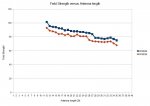
Summary of the results are in the attached spreadsheet, where I have indicated in dB terms how much better that various modes and radios are when compared to the RFM22 data packet transmission and reception.

The FSK RTTY kept working when the transmit power was some 26dB lower than the RFM22 packets. At that power level, the slow Morse beacon was barely audible, listen to the enclosed MP3 file, the Morse being sent was just 'A' plus the digit of the power level number.

Whilst the FSK RTTY will provide for far longer range than the RFM22 data packets, it is relatively power hungry, approx 6 seconds at 100ma to transmit 20 bytes of data. Without a tracking antenna setup you also need to contend with large changes in the audio tones due to the Doppler shift changing. This should be manageable at the beginning and end of a satellite pass as the Doppler shift is relatively constant.

The cheap DVB USB dongle (£6) was a credible performer, but needs a low noise amplifier for long distance work.

By far the easiest receivers to use were the software defined radios. The SDR# software displays the RF spectrum around your chosen centre frequency and you will often see the satellite transmissions (SWISSCUBE and ITUPSAT1 for instance) before you can hear them, making dealing with Doppler fairly easy. When you see the transmission you just click the mouse onto the signal to tune the radio.

The FSK RTTY should be a good mode for balloon tracking, where a LOS range of 500 - 1000km ought to be possible.

No firm news on the satellite launch yet, the PICAXE satellite is due to go up as part of MRFOD payload that Unisat 5 is carrying;

http://space.skyrocket.de/doc_sdat/unisat-5.htm

Unisat 5 is on the same launch as the Funcube satellite, see the TBD section at the bottom;

http://space.skyrocket.de/doc_chr/lau2013.htm
 

Attachments

manuka

Senior Member
srnet: Take a bow on your great posting! Any chance other weak signal modes can be put to the test as well? Some can decode (slow) signals from beneath the band noise of course. FWIW I've had great fun Spectran decoding 08M generated Hellschreiber messages =>www.picaxe.orconhosting.net.nz/smthell.htm

For those who've had a sheltered life (myself included) refer here for $50SAT background. Stan.
 

srnet

Senior Member
The website name was registered by me, just in case. Only £2 a year. One day I may add some real stuff to it.

The picture shows the PCB, the battery is shown for comparison, we are planning to use a slightly smaller one, KLIC 7002. On top of the PCB there is a maximum power point tracker for the solar panels. There are two of these in the states already, one for a battery powered power board, the other an alternative one using Supercaps. I dont have a decent picture of the assembled bird, there have been some issues with the PCBs for the solar panel mounting (in the US).


If time has allows, the PCB might be changed to one with both the RFM22B (100mW) and RFM23BP (1W). The higher power device should substantially improve the chances of the data packet link working, some of the much larger satellites (Cubesats !) use 1W data modems.
 

Attachments

Last edited:

srnet

Senior Member
Any chance other weak signal modes can be put to the test as well?
Could do, I guess Spectran might decode slow signals at very low power from the RFM22, but power in this bird is fairly limited as the solar panels aint that big so real slow transmissions would use too much power.

Power consumption of the RFM22 from 2odBm is approx 97mA, 61mA, 46mA, 35mA,28mA,24mA,22mA,19mA, as the power is reduced in 3dB steps.
 

Paix

Senior Member
Given the options I would recommend a modest gain antenna which would allow for reliable Armstrong mode antenna tracking. I feel that 6dBi to 9dBi would make all the difference, compared to a static colinear. Gain, but not overly directional three to five elements. Where you will definitely benefit, particularly if you are using RTTY is using Ham Radio Deluxe (HRD) to control the GS receiver tuning (FT817) for the doppler shift which is likely to be around plus 6kHz to minus 6kHz of the assigned frequency during the satellite pass. HRD's Rig control works fine under WINE, but other features and antenna pointing don't.

I take it that you have signed up for an account with space-track.org for TLE data? There are other sites that will supply the data, but they obtain it from space-track.org, which is run by the USAF (I believe) in NY. (any password issues etc. are dealt with during office hours, so don't bother champing at the bit for answers on a weekend) They are likely to have the details earlier than others after separation when there can be some confusion as the packages separate and the NORAD # is allocated.

I run Orbitron and it's great for tracking, but uses DDE for antenna and receivers and I'm not into that. I would just love something just to squirt TX/RX and antenna pointing AZ/EL as an ASCII data stream for me to sort out, as I'm sort of text based :) I think that HRD is more straight forward in that respect.

I appreciate your desire to use the RFM22(?) GSReceiver, but for "backup" a decent comms rx is good insurance as your object must be to maximise the results from each available pass.

Have you done any recent listening for a satellite, such as Delfi-c3/Oscar-64 on 145.870MHz Norad # 32789 to refresh your doppler and signal strength memory? It has no batteries and so can only be heard on passes when the satellite is in sunlight. Transmit power believed to be approx 1W

Some time prior to the launch, will you announce downlink frequency once ITU regulatory frequency coordination is complete and can you post a sample/specimen telemetry mp3 file to hopefully check out the receive setup of supporting amateur radio ground stations?

If I've asked any ot this before then please either forgive or ignore me. :) Time to dust off the kit.
= = =
Good on the spreadsheet. Impressed at the improvement from use of the LNA and not surprised at the performance of the FT817 in the mix.
I think that I heard tones among the noise, but it was barely perceptible. The presence of tones that is, not the Morse, I didn't get anywhere near hearing anything coherent, just a glimpse of tone amongst the noise.
 
Last edited:

John West

Senior Member
"Armstrong mode" took me a moment to figure out. Here in the USA we sometimes refer to an "arm-strong rotor" for pointing our beam antennas when out in the field.
 

manuka

Senior Member
A near bewildering number of digital & "fuzzy" modes abound - check the likes of this Naturally tradeoffs on ease of generation & decoding,TX power, satellite pass time, band noise & Doppler shift etc arise. No doubt you are up with greater power etc that hams are allowed ? Stan. ( ZL2APS)
 

Paix

Senior Member
I merely phrased it badly John, it was the Armstrong Rotator that I was thinking of, fueled by the occasonal cold beer beer on hot days and hot drinks on cold days.

I was thinking also of the teams at Delft http://www.delfispace.nl/index.php/participation/radio-amateur-participation and Calpoly http://moredbs.atl.calpoly.edu/downloads/cpxdd who actively solicit radio amateur participation in data collection.

I notice that some keen souls still seem to be submitting CP6 telemetry reports although the bird de-orbited some time ago. Perhaps the TLEs in use are out of date and the next bird on the frequency is flying though their ground station footprint . . .

Almost missed your data modes link there Stan.

It would be good to try to read and perhaps be able to contribute meaningful data. Ian ( G0PAi )
 

srnet

Senior Member
I appreciate your desire to use the RFM22(?) GSReceiver, but for "backup" a decent comms rx is good insurance as your object must be to maximise the results from each available pass.

Have you done any recent listening for a satellite, such as Delfi-c3/Oscar-64 on 145.870MHz Norad # 32789 to refresh your doppler and signal strength memory? It has no batteries and so can only be heard on passes when the satellite is in sunlight. Transmit power believed to be approx 1W
The future is digital.

If such small satellites are to be viable, it becomes almost essential to use digital methods for transmitting data. The FSK RTTY is clearly very effective, but it uses about 40 times the battery power of the same amount of data as a digital packet.

There is no certainty that the RFM22 telemetry will be good enough for the average user to receive, uplink just needs enough power. However it is important is to know how effective the solar panels and battery are, if you cant power a satellite you cant do useful work. So there is a combination of adjusting the slow Morse beacon to indicate good\bad battery and solar charge, plus sending the important battery and solar panel voltage and current out as fast Morse. Even if the fast Morse cant be decoded in real time, by recording it you can use various bits of audio trickery to recover the data. Heck if you slow down the playback you can decode it by ear.

The students at Morehead do have access to a satellite track station, there was a discussion about disconnecting the antenna feed from one of their big dishes and plugging it into the SMA socket on one of my PICAXE boards .........

I have been listening to SWISSCUBE, that has a 100mW CW beacon. The doppler shift is as expected, but the rate of change as it passes overhead is around 150Hz/sec, makes decoding FSK RTTY a bit tricky.

We have a frequency allocation, and the details will be published once there is a firm launch date.
 

Paix

Senior Member
There were several points that I wanted to make, 1W as you will be aware is pretty much a standard, so anything approaching that figure will have what might be seen as a generous link budget, so others will know know ahead of time that they have sufficient system gain to make it worthwhile listening or time to build that new antenna before T- 0 arrives.

The fact that the examples provide decoding software is mute, but that the method required to capture is widely known to a potential audience ahead of time, even if the telemetry decoding scheme isn't. The last thing that you would need is Photoshop telemetry submissions to waste your team's time or potentially mislead.

I don't know about disconnecting a big dish, but a "T" would be worth anyone's eye teeth I guess.

OK on the SwissCube QAP, you are obviously aware and up to speed. Forgive my concerns and for voicing them from time to time, You obviously have the bases covered and more than your fair share of relevant experience. Your patience placating Jimminy Cricket rattling in your ear is noted and appreciated.

I agree that the capture of a coherent FSK signal and the receiver tracking control to achieve it is relatively demanding and would certainly make for a pretty closed eye diagram.

Super project, I will watch, quietly, with great excitement. I will go and suck up some SwissCube info with a view to getting myself up to speed.It's been a couple of years since I had a stab at Delfi-3C and CP4 which were my original real inspiration in satellite matters.
 

srnet

Senior Member
Just been doing some dipole antenna testing of the combined RFM22B (20dBm) and RFM23BP (30dBm) PCB.

I was checking how the length of the dipole elements affected the received field strength. The two devices share a common antenna connection via an antenna switch (AS169). The dipole was made with steel tape measure rule, common for this type of antenna.

The graph shows field strength as -dBm, so a lower number mean stronger signals. From the graph, I ought really have started at 40cm.

The difference between the 'best' length of 35cm and the calculated length of 17cm (437Mhz) was very significant, 17dBm for the RFM22B and 16.5dBm for the RFM23BP. Cut the antenna according to the wavelength\frequency formula and your losing a lot of signal.

This really does need to be checked out in an anechoic chamber ........
 

Attachments

manuka

Senior Member
Was this a classic ½ wave centre fed dipole? When velocity factor is considered then at 437 MHz 35cm should be ~a full wavelength. What other antenna elements were present? Stan ( ZL2APS & ~50 years a dipole wrangler)
 

manuka

Senior Member
I respectively suggest some rechecking (& a posted picture?) may be in order. In 2012 I'd a student who even confused mm & inches (arising from his dual standard tape measure) when constructing a 433 MHz Yagi. Upon presentation we could see at a glance that it's dimensions were over twice (2.54 cm =25.4 mm = 1 in) the intended !
 
Last edited:
Top