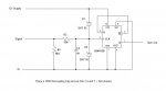
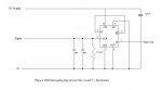
Not likely, but 10K will not work because it forms part of a voltage divider with the 24K input resistor. The signal voltage will then be too low ..... unless you change the supply voltage to the Flip flop to be about 5v.
A 100K would work ok but, will probably not solve your problem, which I am guessing is a poor ground on either set or reset or on the gnd pin of the 4013 itself.
Unless ... the 4013 has been blown by transients on the 14.4 power source. Older CD4000 series device can work up to 15V and the Texas Instruments series is good up to 18v. All bets are off on cheap Asian Knockoffs.
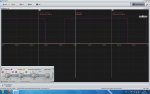
I checked grounds - all of them should be okay, my multimeter is showing 0 ohm between all of the pins that are grounded and the vehicle ground. I've lost all hope of making this work - everything is as it should be, it must be my rotten luck. I've tried 4 ICs, the fifth one I tried had a resistor on its supply rail just to see what that does - I could see some voltage spikes before the resistor, but everything after it looked much smoother and cleaner. That didn't work either. All of the FFs don't react to any voltage changes on CLK input, yet they do react if SET pin goes high. They also output some "random" looking square waves if I change the pull down to something smaller, like 10k and just connect the signal directly. If the pull-down is anything higher - no reaction. This didn't work from the beginning, and when it worked it was some sort of a miracle. I must say, though, that when it worked, I tried with that chip for several hours and it just started working. It stopped working randomly. The second time I managed to get this to work everything was fine on the breadboard, but then it didn't work when i soldered everything on the stripboard. It might be that these chips are very sensitive, or it might be something else.
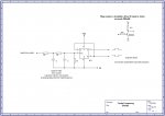
Is there an easy way to check if the FF is still working? If pins 4,6 and 7 are grounded, pin 14 is connected to the supply, pin 5 to pin, I should see a change on both pin 1 and 2 if I apply voltage to pin3?
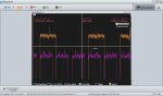
Checked the FF on a breadboard and it does switch states on both Q and Q- when I apply voltage to Pin3. It looks like there's something wrong with the CLK signal from the ECU - I've replaced the 1M pull-down with a 76k and now I'm getting a random looking output - upon looking closer with the scope, it seems to also pick up the noise and react to it. If I use 1M as a pull-down and 24k in series with the signal, then it just does not react to it. I might need to somehow find the right resistor values. Maybe use 1n caps?
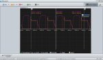
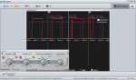
EDIT: Success! Left the 76k as a pull-down, fed the signal without any resistors and used a 1nF cap. It's giving me the result I needed. Now I need to see if this will work on the stripboard prototype, as I still have 1M as a pull-down there and a 24k in series with the CLK input.
")