cactusface
Senior Member
Hi Folks,
The 20M2 greenhouse data logger is coming along nicely, I hope to record 2 temps (in & out), light. If I get really cleaver even wind speed, etc.
While I was looking at the Bitsbox website for a few bits I spotted this Humidity sensor and @ only 80p got a couple, a bit different to others that cost about £12+
But I'm not too sure how they work?? It seems there is a change in resistance with RH and TEMP, that's OK. But then it also mentions a change in FREQ and an operating voltage of 1V max.
Or have I got it all wrong, perhaps someone can tell me how THEIR humidity sensor works.
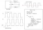
Data sheet attached.
Any help welcome, Thanks.
Mel.
The 20M2 greenhouse data logger is coming along nicely, I hope to record 2 temps (in & out), light. If I get really cleaver even wind speed, etc.
While I was looking at the Bitsbox website for a few bits I spotted this Humidity sensor and @ only 80p got a couple, a bit different to others that cost about £12+
But I'm not too sure how they work?? It seems there is a change in resistance with RH and TEMP, that's OK. But then it also mentions a change in FREQ and an operating voltage of 1V max.
Or have I got it all wrong, perhaps someone can tell me how THEIR humidity sensor works.
Data sheet attached.
Any help welcome, Thanks.
Mel.
Attachments
-
89 KB Views: 64
")