Hi Technical & hippy,
It's good to know that the PIC '16 bit register read' is being used, that eliminates one source of the rollover problem, but the problem is still there !.
I can envisage two ways that the PICAXE firmware could be written :
1 - The PIC 16 bit register is copied to the PICAXE 'timer' variable only when a 'timer' or '#timer' instruction is evaluated in an expression.
The copy can take any number of PIC instructions to execute, but the 16 bit value will be fixed throughout each 'timer' or '#timer' evaluation, because it has been read once with a single PIC instruction.
This does mean that a single expression with multiple 'timer' or '#timer' elements could have different values in each element, but they would all be consistent, with no rollovers.
2 - The PIC 16 bit register is copied to the PICAXE 'timer' variable in the background, at some level that can overlap the evaluation of the 'timer' instruction.
Evaluation of the 'timer' instruction then involves normal firmware byte-by-byte transfers from the 'timer' variable, but the variable could change between these, so rollover artifacts are possible.
The two methods have pros and cons.
Method 1 has specific firmware requirements for when an operation on the 'timer' variable is required, which means a departure from the 'normal' instruction interpreter flow, but has no drawbacks for the user.
Method 2 allows the 'timer' variable to be treated just the same as any other variable ( for reads anyway ), which does not add any complexity to the interpreter, but has the rollover issue.
This second method seem similar to what Technical says here :
It's a unqiue issue to the 'timer' variable as it can change 'in the background' when other things are going on.
But I do not agree with what the below statement says :
... you could argue that the timer variable should be prevented from changing when it is being read/written during any other BASIC command (such as w1 = timer). The problem with that is you can then end up missing events, and timer becomes less accurate.
Setting a flag in the intepreter to inhibit changes to the 'timer' variable, as opposed to the PIC timer register, will :
(a) not stop the PIC hardware from counting, so timer accuracy is not affected.
(b) not prevent the FFFF-0000 interrupt, so the usual 'timer' overflow still occurs.
(c) not miss any events, unless the user writes expressions like 'IF timer = ', which could be seen as bad practice anyway.
Anyway, it's good that we've found this issue, and Rev-ed are taking it on board.
And for hippy :
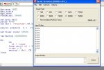
I think you've recognised what is happening now - the timer is going from $2FF to $300, but gets misread as $3FF (1023) so exits the DO-LOOP as > 1000, but when it's subsequently printed it's the correct $300 (768) value that's shown.
Yes that's it, and there is a way to prove it.
The loop should run a fairly fixed number of times if it always exits correctly at 999. At 768 it will be 25% low, so putting a count inside the loop, then test it after exit, would show this.
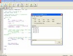
Another method would be to continuously sertxd #timer out to a PC, which would then compare the incoming values and spot discrepancies. ( But it's cool to get the PICAXE to diagnose itself ! )
Don't you just love debugging 'under the hood' ?

 100.5 KB Views: 27