Odd input issue - 08M2

Jeremy Harris

Senior Member
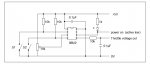
I've knocked up a simple circuit to control a BLDC motor controller. It does two things, it converts a throttle pot to the right voltage range for the controller throttle input and it has an auto-park capability to detect the position of the motor shaft (using a Hall sensor switch) and turn the power off when the shaft has motored (slowly) to the right position (it's for a boat, where I want the two blade prop to be vertical when the power is turned off).

The first version used c.3 as the power switch input (S1 in the drawing) and c.5 as the shaft position switch input (S2 in the drawing, both are active low). This didn't work, with the code only working after the shaft had been rotated by hand until c.5 went low. For some reason the state of c.3 was ignored until c.5 had been taken low, then it worked normally.

The final version (code attached) has the functions of c.3 and c.5 reversed and works as designed.

It's not a particular problem (although it has had me scratching my head for an hour or two) but can anyone see why reading the state of c.3 was ignored when I had that as the "power on" (active low) switch input?

Code:
;This code works with c.3 and c.5 swapped over but doesn't work with c.3 as the power switch input and c.5 as the shaft position switch input - don't know why

SYMBOL Throttle = w0

#picaxe 08m2

init:

	DISCONNECT							;disable serial input scanning on pin c.5
		
	
main:

	IF pinc.5 = 0 THEN GOTO running			;power switch state check and run normally
	IF pinc.5 = 1 AND b2 = 0 THEN GOTO park		;power switch state check and park flag check - park prop if not already parked
	IF pinc.5 = 1 AND b2 = 1 THEN GOTO stopped	;power switch state check and park flag check - turn off controller if already parked
	HIGH c.1							;error trap - turn off controller and return back to this loop
	GOTO main


running:
	
	LOW c.1							;turn on controller power
	READADC10 c.4,Throttle					;read throttle setting from throttle input and scale for controller output range (input range is 0 to 1023)
	Throttle = Throttle * 10				;multiply to allow math for scaling
	Throttle = Throttle / 53				;scale to give max throttle voltage of 3.4 V
	Throttle = Throttle + 82				;add 1 V offset to remove dead period from throttle at start
	PWMOUT c.2, 99, Throttle				;99 sets 10kHz on timer, max duty cycle range on PWM is 0 to 400
	b2 = 0							;reset parked flag to un-parked
	GOTO main


park:

	Throttle = 120
	PWMOUT c.2, 99, Throttle				;set slow speed to rotate prop to correct position
	
park1:	
	IF pinc.3 = 1 THEN GOTO park1				;check for Hall active, loop quickly to detect parked position
	HIGH c.1							;turn off controller and set throttle to zero
	Throttle = 0
	PWMOUT c.2, 99, Throttle
	b2 = 1							;set parked flag
	GOTO main
	
stopped:

	HIGH c.1							;turn off controller and set throttle to zero
	Throttle = 0
	PWMOUT c.2, 99, Throttle
	GOTO main
Basic throttle park circuit.jpg
 

PaulRB

Senior Member
Jeremy,

I wonder if, when c.5 was the shaft position, the program would not run because the picaxe was waiting to be programmed? The DISCONNECT command would not prevent this because as soon as power is applied to the picaxe, it will check to see if c.5 is high before executing the DISCONNECT command, and it would be high becuase of your 10K pullup resistor. As soon as the shaft was rotated and c.5 went low, the picaxe gave up waiting to be programmed and starting running the current program.

Then later when c.5 was the power switch, the same thing is happening, but because when you press the switch the program starts running, it appears to be doing what you expect?

If I'm right, the lesson is not to connect anything normally high to c.5.

Could you have wired your switches from V+ to the C.3 and C.5 pins with pull-down resistors? You would then also have to change your code to check for 1 instead of 0 and vice-versa.

Out of interest, why is it important to have the prop blade vertical when power is off?

Paul
 

hippy

Ex-Staff (retired)
The DISCONNECT command would not prevent this because as soon as power is applied to the picaxe, it will check to see if c.5 is high before executing the DISCONNECT command, and it would be high becuase of your 10K pullup resistor.
That seems a credible analysis of what is happening.


If I'm right, the lesson is not to connect anything normally high to c.5.
Correct; C.5 must not be high at power-on.

Could you have wired your switches from V+ to the C.3 and C.5 pins with pull-down resistors? You would then also have to change your code to check for 1 instead of 0 and vice-versa.
That works, but there's still a potential for the switch to be closed and C.5 high at power-on. The best bet would be pull-downs as suggested, but instead of the other end of the C.5 switch to +V, take it to an output pin which can be set high after the DISCONNECT is issued.
 

AllyCat

Senior Member
Hi,

Or connect one of the "output" lines to the Programming Output pin, to free up one of the I/Os for the use of S1? And maybe even use the internal "weak pullups".

Cheers, Alan.
 

Jeremy Harris

Senior Member
Thanks folks, I am sure that this must be the reason. It had me scratching my head for a fair while, as I couldn't see any problem in the code or the circuit.

I've just done an experiment with the original circuit, but with the "power on" switch sense reversed, so c.5 is held low and is pulled high by the switch. This works fine, so it must indeed be the fact that the DISCONNECT command doesn't have any effect until c.5 is low. It might be worth noting this in the M2 documentation, as I doubt I'll be the only one trying to use the serial input as an additional normal input and encountering this particular quirk.

I simply reversed c.3 and c.5 for the final circuit and this got it working OK.
 

Technical

Technical Support
Staff member
the DISCONNECT command doesn't have any effect until c.5 is low. It might be worth noting this in the M2 documentation, as I doubt I'll be the only one trying to use the serial input as an additional normal input and encountering this particular quirk.
It's not that the disconnect doesn't have any effect, it's the fact that the user's BASIC program cannot start at all if the serial download pin is high at reset. That is because you are basically doing a 'hard-reset' - see the manual for more details.
 

Jeremy Harris

Senior Member
I take the point, and now understand why this happens, but the M2 application note and the manual suggests that c.5 can be used as a standard input, and makes no mention of this limitation when mentioning its use as a general purpose input, quote:

"However there are certain special conditions to this use:
1) The program must contain a ‘disconnect’ command. This command prevents
the PICAXE chip from scanning the serial in pin for new program downloads.
If you do not add this command the PICAXE will reset when the switch is
pressed.
2) After a ‘disconnect’ command is used it will be necessary to perform a poweron
‘hard-reset’ to download a new program.
3) The switch must be open during a new program download.
Due to these special requirements it is generally better, wherever possible, to
reserve the serial in pin for dedicated programming use. Only use as a general
purpose input when all other pins are already used."
 

sid

Senior Member
Using pinc.5 as an input on an 08m2

I too have just been caught out by the PICAXE-M2 information sheet that states.....
Code:
The serial input pins can now be used as 1 or 2 extra input pins, giving up to 2 more general purpose input pins for your project
Having found that c.5 does NOT act like a normal input pin, I searched manual 1 and found the following
Code:
Appendix D – Configuring PICAXE-08/08M/08M2 Input-Output Pins
The PICAXE-08 microcontroller has 5 input/output pins. Unlike the larger
PICAXE microcontroller (where the pins are pre-defined) the user can select
whether some of the pins are used as input or as outputs.
Pin 0 must always be an output, and pin 3 must always be an input (this is due to
the internal construction of the microcontroller). The other 3 pins can be selected
to be inputs or outputs, and so the user can select any input/output combination
between the limits of 1 input-4 outputs and 4 inputs-1 output.
In addition pin 1 also contains a low-resolution analogue to digital converter and
so can be used as an analogue input pin if required.
Important - Don’t Get Confused!
The input/output pin numbers are NOT the same as the external ‘leg’ numbers, as
the input/output pin numbering follows the microcontrollers manufacturers port
allocation. To avoid confusion this manual always talks about ‘legs’ where
referring to the external physical location of the input/output pin.
Leg Description Notes
1 Positive Supply, V Use a 3V to 5V battery pack/supply
2 Serial In Used for the program download
3 Pin 4 Input or output
4 Pin 3 Input only
5 Pin 2 Input or output
6 Pin 1 Input or output
7 Pin 0 / Serial Out Output only. Also used for download
8 Ground, G Connect to the power supply (0V)
Which contradicts the info in the PICAXE-M2 information sheet which leads one to believe that all 6 pins are usable
Even the pinout diagram shows c.5 as an (in)put
Perhaps the manual/data sheet could be updated to be a more clearer on this point.

As for my project, back to the drawing board and finding another pin to use as an input
 

Jeremy Harris

Senior Member
Did you miss page 46 of the part 1 manual?
http://www.picaxe.com/docs/picaxe_manual1.pdf
Worth noting that that page makes no mention of the need to ensure that c.5 is not allowed to be high at power on if it's used as a general purpose input, unlike the other input ports. I'd read the manual (the current version) before being caught out with this. The inference from the manual and M2 data sheet is that c.5 can be used as a normal general purpose input, without restrictions other than the need to use a switch or link to connect the programming connector.
 

sid

Senior Member
Worth noting that that page makes no mention of the need to ensure that c.5 is not allowed to be high at power on if it's used as a general purpose input, unlike the other input ports. I'd read the manual (the current version) before being caught out with this. The inference from the manual and M2 data sheet is that c.5 can be used as a normal general purpose input, without restrictions other than the need to use a switch or link to connect the programming connector.
I agree, it was the M2 data sheet that really pointed me in the wrong direction
referring to an out of date manual didn't help though
 

Technical

Technical Support
Staff member
Yes, that point will be added in the next version. However once you understand that if the pin is high upon powerup the 'disconnect' command will actually never process, the reasons why this is necessary become clear.
 

sid

Senior Member
Another misdirection is on p211 of manual 2 to do with servo control, which states....

Function:
Pulse an output pin continuously to drive a radio-control style servo.
On M2 and X2 parts the servo commands only function on portB (B.0 to B.7)

However the 08m2 data sheet labels all the pins as portC
unless I'm missing something
 

nick12ab

Senior Member
In that case shouldn't the data sheet say portB rather than labelling them as portC.
I'm just pointing out a contradiction in instructions
Maybe. That decision is made by Rev-Ed but I agree that it could be made clearer.

PortB and portC are the same because the pin constants are the same.
 

westaust55

Moderator
The PICAXE manuals in several places in Manual 1 state:
Notes:
1) The 10k/22k resistors must be included for reliable operation.
DO NOT leave the serial in pin floating as THE PROGRAM WILL NOT RUN!
Whether or not the SerialIn pin (also defined as C.5 on the 08M2) is utilized as an input, as has been discussed on this forum many times in the past, the pin must be pulled low for the PICAXE chip to start running the inbuilt BASIC interpreter.
AS already suggested but as some further explanation, the sequence can be considered to be as follows:
1. At power-up the PICAXE tests the state of the SerialIn pin and if in a high state the firmware enters the program download mode. IF the SerialIn pin is low then the firmware enters BASIC interpreter mode. On entering the BASIC interpreter mode, the interpreter must first perform some housekeeping such as clearing variables before execution of the Users BASIC program starts.
2. During operation, unless the DISCONENCT command has been performed, the PICAXE regularly checks the status of the SerialIn pin and when high stops running the user BASIC program and enters program download mode. Once the DICONNECT command is performed the pin (C.5 for the 08M2) may be used as a general input until such time as the RECONENCT command is performed.
By virtue of the fact that the PICAXE takes a finite time to perform the first BASIC command in the User program the SerialIn pin must be held low initially until the DISCONNECT command is in fact performed.
Hence the start-up situation for the newer M2 and X2 PICAXE parts is no different to the earlier parts where the SerialIn pin cannot be used as a general input at any time.
 

Jeremy Harris

Senior Member
The PICAXE manuals in several places in Manual 1 state:


Whether or not the SerialIn pin (also defined as C.5 on the 08M2) is utilized as an input, as has been discussed on this forum many times in the past, the pin must be pulled low for the PICAXE chip to start running the inbuilt BASIC interpreter.
AS already suggested but as some further explanation, the sequence can be considered to be as follows:
1. At power-up the PICAXE tests the state of the SerialIn pin and if in a high state the firmware enters the program download mode. IF the SerialIn pin is low then the firmware enters BASIC interpreter mode. On entering the BASIC interpreter mode, the interpreter must first perform some housekeeping such as clearing variables before execution of the Users BASIC program starts.
2. During operation, unless the DISCONENCT command has been performed, the PICAXE regularly checks the status of the SerialIn pin and when high stops running the user BASIC program and enters program download mode. Once the DICONNECT command is performed the pin (C.5 for the 08M2) may be used as a general input until such time as the RECONENCT command is performed.
By virtue of the fact that the PICAXE takes a finite time to perform the first BASIC command in the User program the SerialIn pin must be held low initially until the DISCONNECT command is in fact performed.
Hence the start-up situation for the newer M2 and X2 PICAXE parts is no different to the earlier parts where the SerialIn pin cannot be used as a general input at any time.
Yes, I understand that the serial input needs to be held low for the programme to run, and have done for a many years, at least WRT to the various Picaxe versions I've been using for goodness knows how long, but thanks for trying to re-educate me in your own rather supercilious way....................

The specific point here was one that the newer M2 information inferred that c.5 was now (on the M2 Picaxe chips specifically) a general purpose input. The previous limitation that it had to be low for the programme to run seemed to have been superseded from the information provided. It's now blindingly obvious that this isn't the case, and there seems to be general agreement that the information in the manual and the M2 information sheet was a little ambiguous.
 

westaust55

Moderator
The specific point here was one that the newer M2 information inferred that c.5 was now (on the M2 Picaxe chips specifically) a general purpose input.
IMHO it seems straight forward:

The M2 Briefing note states:
More I/O Pins
The serial download pins can now be used as general purpose pins. The new reset command replaces the need for a separate external reset pin. Therefore on 18 pin parts leg 4 is now available as another general purpose input pin.
See: serrxd, sertxd, disconnect, reconnect, reset
And if we look at the "DISCONNECT" command in Manual 2:
Function:
Disconnect the PICAXE so that it does not scan for new downloads.
thereafter the SerialIn pin (pin C.5) can be used as a general IO pin.
 
Top