Stepper stuff

boriz

Senior Member
My stepper kits arrived from DX: http://www.dealextreme.com/p/28ybt-48-stepper-motor-with-uln2003-driver-dc-5v-126409?item=2

This is how the board is wired:


Seem to work fine. I'm driving it at 6v and it's drawing <300mA with no load.

This is the test code I'm using:
Code:
#Picaxe 08m2
'Stepper motor driver test
'Boris Burke May 2012

setfreq m8
dirs=%00010111
do
	b1=b1+2 max 3//3	'b1 is direction control, 2=CW 0=CCW
	for w1=1 to 2060	'seems to be about the right number of steps for 360 degrees
		b0=b0+b1-1//4	'b0 cycles from 0 to 3 for CW and from 3 to 0 for CCW
		lookup b0,(%00011,%00110,%10100,%10001),pinsC
		pause 1
	next w1
	pause 4000
loop
It rotates 360 degrees CW then 360 degrees CCW and repeats. The 5 bits instead of 4 in the lookup is because pinC.3 cannot be an output on the 08m2, so I have to use pinC.4 for the fourth bit.

Question. How can you tell when a step has been missed/slipped due to excessive drag on the spindle?

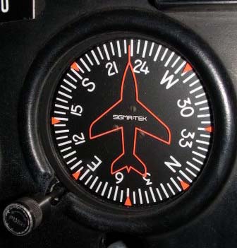
Reason I ask is coz I might use this kit to make an avionics-type heading indicator for my little car using a magnetometer and a stepper to rotate the disk. The stepper can sync/calibrate for absolute position on startup using maybe an optical interrupter thingy. But from then on, I want it to remain in sync without further calibration for hours at a time, keeping true to the commanded compass direction.
 
Last edited:

BeanieBots

Moderator
That's the age-old problem with stepper motors. You CAN'T tell if a step has been missed.
To know for sure, you will need a position feedback device.
The simplest method in common use is an encoder which produces a pulse for each step. You then count the pulses and compare to your stepper position count.
The way printers etc (where position error is not fatal) do it, is to simply drive to a known location identified by a single sensor (opto or microswitch) to periodically 'check' that no steps have been lost. Sometimes, this is only done at power up but sometimes it can be done on each carriage return.
With a device such as yours, there should be no real reason for to ever to lose track. There is very little load and the load is constant. A good design and proper testing to check that you are well within step rate and pulse width parameters will result in an extremely reliable system.
 

boriz

Senior Member
Thanks BB. Kind of figured it would be ok in this app, but just wanted to be on the safe side. Maybe Bluejets was joking.
 

boriz

Senior Member
Next question.

I figure there must be a certain integer number of steps to represent a single complete 360 rev. But I can't seem to find it. It seems to be someplace between 2037 and 2038. Now this could just be caused by the occasional 'slipped step' when starting the rotation or 'overstep' when stopping. I'll try adding acceleration and deceleration routines. But is my assumption correct? There should be an integer number of steps for an exact 360?
 

Technical

Technical Support
Staff member
The website where you bought it would be a good place to start...

- Step Angle: 5.625 x 1/64
- Reduction Ratio: 1/64
So you need 64 steps, each step giving 5.625 degrees. So something is not quite right in your program... or the website!

Or is there a 1/64 gearbox attached? If so the steps in 360 should be 64 x 64? And a gearbox will give you some 'play', introducing inaccuracy.
 
Last edited:

Buzby

Senior Member
My calculation of 5.625 / 64 equates to 4096 steps per 360', which seems a more likely number than 2037.

Have you tried stepping 'x' forward, then 'x' backward ? If you don't end up where you started then you are missing steps.
 

boriz

Senior Member
4096 is two revs.

With this code* I can get perfect results. IE. The mark-on-a-disk always returns to the exact start position. Two revs CW followed by two CCW returning to exact start point repeatedly.

But if I comment out the direction change and let it go just CW then it always goes a little too far. It gains a bit. So 4096 steps is a little bit more than 2 revs.

Whats going on?


*code
Code:
#Picaxe 08m2
'Stepper motor driver test
'Boris Burke May 2012

symbol prefinish=w0		'controls the start of deceleration
symbol finish=w1		'number of steps to the finish
symbol steps=w2			'counts the steps
symbol direction=b6		'2=CW 0=CCW
symbol phase=b7			'counts from 0 to 3 for CW and from 3 to 0 for CCW
symbol speed=W6			'changes with acceleration/deceleration (lower is faster, min 1)
symbol slow_limit=w7	'destination speed when starting and stopping (higher is slower)

setfreq m8				'double the Picaxe clock speed
pause 1000				'wait for the new clock speed to settle (1000=500mS at m8)
dirs=%00010111			'bit 3 cannot be used because I'm using an 08m2
slow_limit=32			'upper limit for slowest step speed during acceleration/deceleration
finish=4096				'number of steps to take
direction=2				'direction switch 0=CW 2=CCW

do
	direction=direction+2 max 3//3				'alternate direction, comment this line for single direction
	speed=slow_limit							'set delay
	for steps=1 to finish						'beging rotation loop
		prefinish=finish-steps+1				'set deceleration point
		if steps<slow_limit then				'if starting
			speed=speed-1 min 1					'then accelerate
		elseif prefinish<slow_limit then		'if stopping
			speed=speed+1 max slow_limit		'then decelerate
		endif									'end acceleration adjustmet to SPEED
		pause speed								'speed of rotation pause
		phase=phase+direction-1//4				'work out the next output bit pattern
		lookup phase,(%00011,%00110,%10100,%10001),pinsC	'move stepper motor
	next steps									'end of rotation loop
	pause 4000									'wait 2 seconds
loop
 

bfgstew

Senior Member
Been reading this with interest.

My thoughts on it are - 1 rev of the motor is 64 steps
1 rev of output shaft is 4096 steps (64 revs of motor), if the gear ratio is X 1/64.

Stewart
 

Buzby

Senior Member
... Two revs CW followed by two CCW returning to exact start point repeatedly.
OK, so this tells us no steps are being missed.
But this test tells us nothing about the gearbox ratio, it could be 10:1, 50:1, 64:1, anything at all.

... if I comment out the direction change and let it go just CW then it always goes a little too far
This would seem to indicate that the gearbox is not exactly 64:1, which is strange.

When you say 'a little too far', is it always exactly the same ?.

Can you 'step back' from 'too far' and count how many pulses over it appears to be ?

( My gut feeling is there is something not right with the gearbox, but I don't know enough about gears to have a specific idea. )
 

bfgstew

Senior Member
How about checking how many steps it takes to do a full rev of the output shaft and working backwards on that outcome? Also see if it is the same conclusion for every rotation to see if there is a missed step?
 

bfgstew

Senior Member
Doubt it at that size of gearbox, it would manifest itself when going CW then CCW, and that seems to be fine according to Boriz
 

boriz

Senior Member
"...checking how many steps it takes to do a full rev..."
Exactly what I've been trying to do!

"...backlash in the gearbox..."
There is some small backlash, but it does not effect the continuous CW mode. If anything, it would effect the reversing mode and it doesn't.
 

bfgstew

Senior Member
Ok, had another thought on this one Boriz.
Mount the stepper motor so the output shaft is through a largish sheet of card, mount a long pointer of some description to the shaft and then run the motor so the pointer ticks like a second hand on a clock, mark each step with a marker pen and you should see any discrepensies. Yes it will take ages but feel this is the easist way to physically check the motor / gearbox for any defects.

I hope you get it sorted soon.

Stewart
 
Top