Jeremy Harris
Senior Member
I've built a few electric bikes now, and the one thing I've never been happy with is the main power switch. Electric bike controllers contain some big capacitors and the switch on surge current is high - high enough to burn out many standard high current switches before long. The solution I've used up to now is to have two switches, one that turns on the power via a resistor to limit the surge current, the second operated a second or two later to short out the resistor. Not very elegant.
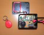
Having been playing with a cheap 125kHz RFID module from Seeed Studio (this one: http://www.seeedstudio.com/depot/125khz-rfid-module-uart-p-171.html?cPath=144_153) I realised I could make a neat unit to switch my electric bike on and off. I already have a handlebar mounted cut-off switch, so using a Picaxe 08M2, some power FETs and the RFID module I made this little box:
The schematic for the unit is here:
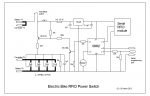
and the code is here:
In operation the unit is powered on by the handlebar mounted cut-off switch, which then sets it running around a loop giving a short beep while it's waiting for a valid RFID tag to be waved past the sensor coil in the lid of the box (the box is mounted under the saddle of the bike). When a valid tag is detected the beeper gives a 1 second beep, the FETs are turned on slowly (the 1µF capacitor on the gates slugs the turn on time down) and the bike is then powered on. The programme stops at this point. When the handlebar cut-off switch is operated, the FETs and the Picaxe turn off.
The RFID tag is small enough to fit neatly on a key ring, and the whole unit is inconspicuous enough that no one would easily guess what it does. I used four FETs in parallel, not to get a high current capability, but to ensure that the on resistance is very low, to reduce power losses. The bike can draw up to around 30 A at full throttle, and I didn't want to waste power as heat in the switch.
This is the second Picaxe project on this bike, there is an 08M inside the controller that measures the current drawn from the battery, calculates amp hours remaining since last charge and displays the state of charge on a small meter on the handlebars. That's been on the bike for a couple of years and has proved invaluable in knowing how much range I have left.
Jeremy
Having been playing with a cheap 125kHz RFID module from Seeed Studio (this one: http://www.seeedstudio.com/depot/125khz-rfid-module-uart-p-171.html?cPath=144_153) I realised I could make a neat unit to switch my electric bike on and off. I already have a handlebar mounted cut-off switch, so using a Picaxe 08M2, some power FETs and the RFID module I made this little box:
The schematic for the unit is here:
and the code is here:
Code:
;Electric bike RFID power switch


;The code below loops around giving a short beep every second until a valid key is detected, when it then turns the power on,
;beeps for one second and the programme ends, leaving the power switch FETs turned on.

;The code restarts at next power on via a handlebar mounted cut-off switch that also supplies the power to the unit.
;With the handlebar switch off the FET power switch is also off.

;The first byte sent by the RFID reader is always 02h, and is ignored in the code below
;The next ten bytes are the RFID tag code in ASCII, read into bytes b1 to b10
;The read value is compared with the tag code obtained from the serial terminal during set up
;after ten ASCII data bytes the unit sends two bytes of checksum and a single byte for end of transmission, 03h, also ignored in this code


#picaxe 08M2

setfreq m8		;Needs to run at 8MHz in order to get 9600 baud for RFID reader output


main:

	serin [2000,no_valid_code],c.4,T9600_8,b0,b1,b2,b3,b4,b5,b6,b7,b8,b9,b10,b11,b12,b13 ;read RFID tag number into variables b1 to b13

	IF b1="0" AND b2="1" AND b3="0" AND b4="0" AND b5="0" AND b6="5" AND b7="3" AND b8="5" AND b9="3" AND b10="B" THEN ;Dummy tag number to detect (use real one obtained from code below)
	HIGH c.2	;turn on beeper
	HIGH c.1	;turn on FET switch
	PAUSE 2000
	LOW c.2	;turn off beeper
	ELSE
	LOW c.1	;keep FET switch turned off when no valid tag
	LOW c.2	;keep beeper turned off when no valid tag
	PAUSE 2000
	GOTO no_valid_code
	ENDIF
	END		;comment this out during set up so that the code loops continuously to read tag ID numbers

no_valid_code:

	HIGH c.2	;turn on beeper
	PAUSE 20	;keep beeper on for 10 mS
	LOW c.2	;turn beeper off


	;Uncomment the code below to read tag ID numbers via the serial port and terminal when setting the unit up for a new tag ID

	;setfreq m4 ;slow picaxe back down for serial comms to work at 4800 baud (not needed when line below commented out)

	;sertxd (#b0,",",b1,",",b2,",",b3,",",b4,",",b5,",",b6,",",b7,",",b8,",",b9,",",b10,",",#b11,",",#b12,",",#b13,cr,lf)

	;setfreq m8	;speed clock back up again to run at 9600 baud for RFID reader


GOTO main ;loop back to main programme if tag read isn't valid or if no tag detectedThe RFID tag is small enough to fit neatly on a key ring, and the whole unit is inconspicuous enough that no one would easily guess what it does. I used four FETs in parallel, not to get a high current capability, but to ensure that the on resistance is very low, to reduce power losses. The bike can draw up to around 30 A at full throttle, and I didn't want to waste power as heat in the switch.
This is the second Picaxe project on this bike, there is an 08M inside the controller that measures the current drawn from the battery, calculates amp hours remaining since last charge and displays the state of charge on a small meter on the handlebars. That's been on the bike for a couple of years and has proved invaluable in knowing how much range I have left.
Jeremy