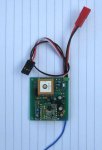
This is the code that uses a 28X2 to read Latitude and Longtitude from a GPS module and transmits the absolute location of the module or its distance and direction as either fast 60WPM Morse or slow 15WPM Morse.
Based on low power true line of sight tests at 8.2km, at maximum output power (100mW) the line of sight range for decoding the Morse, using an UHF Amateur band reciever is in excess of 50kM for the auto decoded Morse (via the soundcard of a Laptop\Netbook), or if you can read the slow Morse by ear, the line of sight range should be 1000km or so..
The module has a distance calculation range of a little over 1 Degree Lat\Long in either direction, so approximatley 120kM in the UK.
The module can drive either a AXE133Y OLED\LCD display, showing current and home lat and long plus distance and direction, or can send the position data and a pile of debugging stuff, to an OPENLOG micro SD card logger, this data is output in CSV format.
The code runs over two slots, and there is an enhanced version of the GPS collector program which uses a timer or checks an model radio control pulse, to determine 'lost' status as a lost model locator, as soon as the code for that is checked out it will be posted also.
Many thanks to forum member Armp, who provide some of the routines use to persuade an integer only PICAXE to do some trigonometry. There is a bit of Mr Leach in there too.
The code could no doubt be improved upon, the short distance (under 1km) resolution could be better. In general the direction calculation is accurate to 1 degree.
Attachments
-
 52.4 KB Views: 137
 -
19.4 KB Views: 150
Last edited: