The RTTY decoder is designed to display radio teleprinter signals on a 16 character by 2
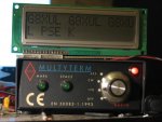
line LCD module based on the Hitachi 44780 controller. I used a BATG Multyterm terminal
unit for the tone decoder, although any of the many TU designs found on the Internet could
be used. With the advent of PC based sound card input software such as MixW these are otherwise redundant.
Initial testing was performed using the soundcard output from MixW PC software. On air
testing was mainly on the 20m amateur band where the center of activity is 14.080MHz.
Solid copy was also received from the German weather service DDK9 on 10,100.8 kHz.
The code consists of 4 modules, an interrupt driven input module, circular input buffer,
lookup table and lcd driver.
Hardware is built on veroboard with plug and socket to the lcd and to a small daughter
board with the RS232 to 5V logic convertor. This allows for the addition of a dedicated
tone decoder (proberbly using an NE 567 pll) later....
I used a 20X2 because I had one. Some of the commands are not available on M2 parts but
little recoding should be necessary if you wanted to try. I run at 16MHz because a)it was
fast enough b)because I couldn't get the LCD to work faster (yes I did change the timings).
This is my first attempt at picaxe coding so constructive critisism is welcomed. Let me
know if you build one.
Code has to be split to fit post. Join pt1 and pt2 together to complete program.
Code:
#picaxe 20x2

; RTTY Decoder (45.5/50 baud)
;
;Baudot code has 5 data bits, 1 start bit and at least 1.5 stop bits.
;Start bit is 0
;Stop bits are 1
;

;Look for idle
;wait for start bit
;30ms later look for data 1
;clock data into a byte variable every 20ms
;look up the ascii
;add to circular buffer
;start again

;Here's the ITA2 code

;	LTR 	FIGS	  lsb

;0 	NUL 		00 00000 NULL, Nothing (blank tape)
;1 	E 	3 	01 10000
;2 	LF 		02 01000 Line Feed (new line - translate as space )
;3 	A 	- 	03 11000
;4 	SP 		04 00100 Space
;5 	S 	' 	05 10100
;6 	I 	8 	06 01100
;7 	U 	7 	07 11100
;8 	CR 		08 00010 Cariage Return
;9 	D 	ENC 	09 10010 Enquiry (Who are you?, WRU)
;10 	R 	4 	0A 01010
;11 	J 	BEL 	0B 11010 BELL (ring bell at the other end)
;12 	N 	, 	0C 00110
;13 	F 	! 	0D 10110
;14 	C 	: 	0E 01110
;15 	K 	( 	0F 11110
;16 	T 	5 	10 00001
;17 	Z 	+ 	11 10001
;18 	L 	) 	12 01001
;19 	W 	2 	13 11001
;20 	H 	$ 	14 00101 Currency symbol (can also be £)
;21 	Y 	6 	15 10101
;22 	P 	0 	16 01101
;23 	Q 	1 	17 11101
;24 	O 	9 	18 00011
;25 	B 	? 	19 10011
;26 	G 	& 	1A 01011
;27 	FIGS 		1B 11011 Figures (Shift on)
;28 	M 	. 	1C 00111
;29 	X 	/ 	1D 10111
;30 	V 	; 	1E 01111
;31 	LTRS 		1F 11111 Letters (Shift off)
;-----------------------------------------------------------------------------

SYMBOL offset = b40
;SYMBOL  letters_start = b40	;pointer to the start of letters lookup table
;SYMBOL  figures_start = b41	;pointer to the start of figures lookup table
SYMBOL  codein = c.1		;Define pin for RTTY input
SYMBOL  testpin = c.0		;Define a testpin for output

SYMBOL  bytee = b12		;This is the character or command to be sent
					;to the display

symbol rttyin = pinsC		;the input port
symbol mask = b42			;bit mask for input
symbol rttyout = b43		;byte containing the ITA2 code of the i/p


;------------------------------------------------------------
;LCD Routine declarations
;------------------------------------------------------------
SYMBOL  getting   = b11		;This is a pointer to the EEPROM
SYMBOL  rsbit     = b13
SYMBOL  presbptr  = b44

SYMBOL char0 = b20		;The line buffer....b20 to b35
SYMBOL char1 = b21
SYMBOL char2 = b22		;Symbols not used in this version,
SYMBOL char3 = b23		;variables are though
SYMBOL char4 = b24
SYMBOL char5 = b25
SYMBOL char6 = b26
SYMBOL char7 = b27
SYMBOL char8 = b28
SYMBOL char9 = b29
SYMBOL char10 = b30
SYMBOL char11 = b31
SYMBOL char12 = b32
SYMBOL char13 = b33
SYMBOL char14 = b34
SYMBOL char15 = b35

SYMBOL charcount = b36		; Cursor position on current line
SYMBOL preserve_char = b37	; Preserve the current character while we move lines

SYMBOL  RSCMDmask = %00000000 ; Select Command register
SYMBOL  RSDATmask = %00000100 ; Select Data register

SYMBOL  RS        = B.2         ; 0 = Command   1 = Data
SYMBOL  E         = B.3         ; 0 = Idle      1 = Active
SYMBOL  DB4       = B.4         ; LCD Data Line 4
SYMBOL  DB5       = B.5         ; LCD Data Line 5
SYMBOL  DB6       = B.6         ; LCD Data Line 6
SYMBOL  DB7       = B.7         ; LCD Data Line 7
;--------------------------------------------------------------------
;Circular buffer defines
SYMBOL cbinptr = b46		;circular buffer input pointer
SYMBOL cboutpptr = b47		;circular buffer output pointer
SYMBOL cbstart = $10		;circular buffer start location in scratchpad
SYMBOL cbend = $17		;circular buffer end location in scratchpad
SYMBOL ascii_in = b48		;ascii character coresponding to rttyout
ptr = cbstart			;set scratchpad pointer to start of buffer
;--------------------------------------------------------------------

;Baudot to Acsii Lookup table

EEPROM $40, ($00,"E",$20,"A",$20,"SIU",$00,"DRJNFCKTZLWHYPQOBG",$00,"MXV",$00)			;letters
EEPROM $60, ($00,"3",$20,"-",$20,"'87",$00,$00,"4",$00,",!:(5+)2$6019?&",$00,"./;",$22,$00)	;figures

;---------------------------------------------------------------------
;Welcome message
EEPROM 6,("G8XUL RTTY      DECODER     ") ;last location is 33
;---------------------------------------------------------------------
setfreq m16 			; setfreq to 16MHz
;Setup pins:
let dirsC = %00000001		;Set port C for the code input
let dirsB = %11111111		;Set port B to all outputs for LCD
let adcsetup = 0			;Disable all ADCs
let offset = $40			;lookup table start
;---------------------------------------------------------------------

let charcount = 0			;first position on the LCD line

;-----------------------------------------------------------------------------
GOSUB InitialiseLcd		;Setup the display


bytee	= $C0 			;Cursor to start of line one
bptr  = 20    			;set variable pointer to b20 (start of line buffer)
presbptr = 20
gosub SendCmdByte

FOR getting = 6 TO 32		;write the welcome message
    READ getting,bytee
    ;sertxd (bytee)
    GOSUB charprint
    pause 100
NEXT

wait 5


SETINT %00000000,%00000010,C		;Interupt when we see a start bit

;-------------------------------------------------------------------------
; Use scratchpad as input buffer. 8 bytes should be enough.
;-------------------------------------------------------------------------

main:
gosub readbuffer				;Loop untill interupted by a start sequence
goto main

;------------------------------------------------------------------------
interrupt:

gosub getchar				;get the character and display it
setint %00000000,%00000010,C		;get ready for the next character
return

;------------------------------------------------------------------------
getchar:
pauseus 6000
mask = %00000001				;put the mask to bit 1
rttyout = 0
for b45 = 1 to 5				;do it one for each bit
IF rttyin BIT 1 SET THEN
rttyout=rttyout or mask 		;set the bit if the input is high
endif
mask = mask * 2	 			;move to the next bit in the mask
pauseus 4000    				;wait for the next bit
next

select case rttyout
case $1F					;if letters received point at letters in lookup table
offset = $40 :return
case $1B 					;if figures received point at figures in lookup table
offset = $60 :return
endselect

;look it up!
rttyout = offset + rttyout		;point to the ascii character

READ rttyout,ascii_in			;do the lookup


if ascii_in != 0 then 			;if it's null, do nothing
;gosub charprint
put cbinptr,ascii_in			;put the character in the buffer
cbinptr = cbinptr + 1			;and increment the pointer
cbinptr = cbinptr AND %00000111	;and roll over if = 8
endif


return

;----------------------------------------------------------------
;read the buffer and send to the display
readbuffer:
b50 = cbinptr - cboutpptr		;test for buffer empty
if b50 = 0 then return			;no character to process
endif
GET cboutpptr, bytee			;get the next char to print from the buffer
gosub charprint				;and put to the LCD
cboutpptr = cboutpptr + 1		;increment the pointer
cboutpptr = cboutpptr AND %00000111	;and roll over if = 8
return
;----------------------------------------------------------------
;
;Display routines follow
;
;----------------------------------------------------------------
Last edited: