Just to add my 2 cents to this money related thread:
http://www.ebay.co.uk/itm/9W-36W-UV-CURING-LAMP-LIGHT-NAIL-DRYER-RED-WHITE-PINK-/270802944277?pt=UK_Health_Beauty_Nails_Manicure_Pedicure_CA&var=&hash=item84b85f0f6d
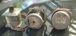
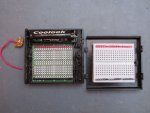
Not exactly your standard kit. I used the one back right, but I imagine the front ones would let you do bigger boards (a problem I now have).
There's a thread all about it for those interested (very long as per most of my threads, so skip to last page). As Dippy points out on that page, it is certainly the cheap route. If I could afford better, I might go for it, but I wouldn't concider the method to be limmiting, only my skill in using it. I can currently achieve sub-mm tracks out of it with very low per-board cost.http://www.picaxeforum.co.uk/showthread.php?12423-UV-lightbox-cheap-equivalents/page26
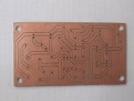
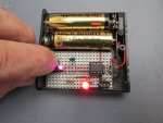
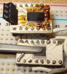
Attached some recent examples, and they had A LOT going against them (mostly, storing the photoboard in sunlight for a year or so).
Cheers,
David.
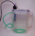
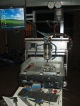
My whole set-up is less than that. I go the UV, photoresist board route. The key is my UV box:and they quote it costed 50 pounds for the boards................absolute madness i think!!!!!
http://www.ebay.co.uk/itm/9W-36W-UV-CURING-LAMP-LIGHT-NAIL-DRYER-RED-WHITE-PINK-/270802944277?pt=UK_Health_Beauty_Nails_Manicure_Pedicure_CA&var=&hash=item84b85f0f6d
Not exactly your standard kit. I used the one back right, but I imagine the front ones would let you do bigger boards (a problem I now have).
There's a thread all about it for those interested (very long as per most of my threads, so skip to last page). As Dippy points out on that page, it is certainly the cheap route. If I could afford better, I might go for it, but I wouldn't concider the method to be limmiting, only my skill in using it. I can currently achieve sub-mm tracks out of it with very low per-board cost.http://www.picaxeforum.co.uk/showthread.php?12423-UV-lightbox-cheap-equivalents/page26
Attached some recent examples, and they had A LOT going against them (mostly, storing the photoboard in sunlight for a year or so).
Cheers,
David.
Attachments
-
 741 KB Views: 88
")