Servo ???

sid

Senior Member
Hello all, its been a while since I was last on here but I've returned with a query regards getting a servo to move slowly.
I'm trying to get a servo arm to move slowly between two points and then back again.
It works up to a point in that the servo does move slowly but not throughout the whole movement, for some reason it appears to speed up for a short part of the journey towards the middle of the arc in both directions
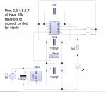
I've attached a circuit diagram and code is pasted below
What am I doing wrong ????

Code:
start:
high b.4
servo b.5,170 				
pause 1000

servo1: 
for b1 = 170 to 130 step -1	
servopos b.5,b1
pause 40
next b1

pause 2000

for b1= 130 to 170 
servopos b.5,b1 				
pause 40	  				
next b1					
pause 2000 					
goto servo1
 

Attachments

The only thing I can think of is that the pulse with does not correlate linearly with the servo arm. Did you try another servo?
 

sid

Senior Member
The only thing I can think of is that the pulse with does not correlate linearly with the servo arm. Did you try another servo?
Good call,
I changed the servo for a brand new one which failed to work at all !
As did the next one !!
The third one however did work and worked as one hoped it would
So that's a 75% fail rate

So although these little servos's from Hong Kong are cheap as chips they obviously aren't that well made
Any ideas where I can buy some decent servos from ?
 

sid

Senior Member
What size / power are you looking for?
e
I'm currently using (according to the label) a 9g micro.
I want to use it to operate a railroad switch so it doesn't have to be that big or powerful, but reliability is a must
Cheers
 

SD70M

Senior Member
@sid

I recently bought 6 of these from ebay for a very similar project to yours.

They all worked out of the box. Individually they worked exactly as required, slow action 30 point movement.

The only problem came with have 6 controlled from one picaxe. Now that too is solved.

HTH, Angie
 

sid

Senior Member
@sid

I recently bought 6 of these from ebay for a very similar project to yours.

They all worked out of the box. Individually they worked exactly as required, slow action 30 point movement.

The only problem came with have 6 controlled from one picaxe. Now that too is solved.

HTH, Angie
Thanks Angie,
They look very similar to the ones I already have but at £10 for 4 its worth a try, cheers
Sid
 

AndyGadget

Senior Member
Hextronik does it for me.

The problem with the eBay sellers is that the items may be cheaper lookalikes of main branded items and you've no idea of the quality of the item they're going to ship as they vary from order to order. I'm extremely satisfied with the Hextronic HXT900 servos from HobbyKing - Very widely used HK based RC parts supplier.
They work well when modified for continuous rotation too. The only downside I've found is the short drive spindle if you're trying to attach something other than the supplied horns to it. As a major supplier it looks like HK have more control over what they're shipping rather than the less specialised eBay sellers.

http://www.hobbyking.com/hobbyking/store/__662__HXT900_9g_1_6kg_12sec_Micro_Servo.html
 

BillyGreen1973

Senior Member
I would suggest looking at the sd21 servo controller that Rev-Ed sell. It can control up 21 servos at once, speed of each servo can be set indevidually, as can angle etc. Startup positions can be set and stored in memory. All this is done via I2C, with the onboard picaxe 18x/m/m2, or from any external I2C capable picaxe. Great product and ideal for modelers. The controller does all the hard work, leaving the picaxe to just issue servo/position commands, then get on with anything else.
 

sid

Senior Member
Another question if I may.
Now I've found a servo that works I'd like to be able to stop the travel of the servo arm automatically when it meets resistance eg: when the point blade of the railroad switch hits the rail against which it is being pushed against, is there a way of detecting this so I can save the position of the servo arm at that point and use that value for the limit of travel further on in the program ?

I had the idea of taking a voltage reading from the power input of the servo and connecting that to an adc input on the 18m2 as I noticed that the voltage changed when resistance was met, however I don't seem to be able to turn this theory into practice. Can anyone advise
Code below and updated diagram attached


Code:
start:
high b.4
servo b.5,150 				
pause 1000

servopos b.5,135
pause 1000

servo1: 
for b1 = 165 to 135 step -1	
servopos b.5,b1
readadc b.6,b2
if b2>245 then high b.3 endif
pause 40
next b1

pause 2000

for b1= 135 to 165 
servopos b.5,b1 				
pause 40	  				
next b1					
pause 2000 					
goto servo1
 

Attachments

srnet

Senior Member
The current drawn by the servo will rise when its meets resistance, but if your power supply drops appreciably when this happens, then the power supply is not good enough.

A far better engineered solution would be a better power supply with a proper current measuring device, although for higher currents the techniques are discussed in this thread;

http://www.picaxeforum.co.uk/showthread.php?20858-Measuring-Current-with-PICAXE-between-20-and-40-Amps-DC-even-possible

If the end point is likley to change at all there are mechanical devices to protect the servo, do a Google search on 'servo saver'

A far simpler solution, if the end point is fixed, is just to set it up and record the end point manually, which is exactly what you would do if setting up servo travel limits on a RC plane.
 

sid

Senior Member
The current drawn by the servo will rise when its meets resistance, but if your power supply drops appreciably when this happens, then the power supply is not good enough.

A far better engineered solution would be a better power supply with a proper current measuring device, although for higher currents the techniques are discussed in this thread;

http://www.picaxeforum.co.uk/showthread.php?20858-Measuring-Current-with-PICAXE-between-20-and-40-Amps-DC-even-possible

If the end point is likley to change at all there are mechanical devices to protect the servo, do a Google search on 'servo saver'

A far simpler solution, if the end point is fixed, is just to set it up and record the end point manually, which is exactly what you would do if setting up servo travel limits on a RC plane.

This video demonstrates what I am trying to achieve (scroll forward to 4mins)
http://www.youtube.com/watch?v=Aj1yhUKBd58
I've made point motors with servos before but It takes ages to set the end limits up and I was intrigued with the way the circuit sensed when the servo arm had reached its limit of travel and wondered how to do that with a Picaxe
 

srnet

Senior Member
This video demonstrates what I am trying to achieve (scroll forward to 4mins)
http://www.youtube.com/watch?v=Aj1yhUKBd58
I've made point motors with servos before but It takes ages to set the end limits up and I was intrigued with the way the circuit sensed when the servo arm had reached its limit of travel and wondered how to do that with a Picaxe
You would need to monitor the cureent the servo is drawing, there is no other feedback from the servo ...........
 

srnet

Senior Member
Probably the eaisest way is to deleiberatly make your stabilised power supply 'bad' by putting a resistor in line with the servo supply, and shorting it out for normal use with a P channel MOSFET.

With the resistor in circuit, the supply voltage to the servo will reduce as the load is increased, as you may have noticed.

What value of resistor to use, and whether the PICAXE can measure the voltage to sufficient resolution, you would need to determine by experiment.

And if you follow the link I gave earlier, you will see another method of measuring current .....,.
 

erco

Senior Member
+1 to Hextronic HXT900 servos, they're the best cheap 9g servos around.

Not sure why Angie's having trouble controlling 6 servos, the M2 series is nearly a servo controller and can handle 8 easily using SERVOPOS, not PULSOUT. http://www.youtube.com/watch?v=HSLktpOkrGs and http://www.youtube.com/watch?v=kF6TwbIT384

As far as pulsewidth vs servo position linearity, that last video shows how linear a good servo is. The blocks are all spaced 7 units of pulsewidth apart, and you can visually tell that the spacing is very uniform.

@sid: Why not just use a limit switch to stop your servo in the desired location?
 

SD70M

Senior Member
Not sure why Angie's having trouble controlling 6 servos, the M2 series is nearly a servo controller and can handle 8 easily using SERVOPOS, not PULSOUT.
@erco
If you'd read what I actually wrote I said "The only problem came with have 6 controlled from one picaxe. Now that too is solved."

The problem I had, which I didn't know about until doing a little research, was that the servo's should be powered by a seperate PS to that of the picaxe but the 0V of both power supplies should be connected.

I'm only controlling 6 servos as I am using 14 I/O pins:
6 for switches (1 for each servo),
6 for servo signals
2 outputs for led indicators for programming mode
2 inputs for programming mode (or may use these for picaxe comms)

Angie
 

srnet

Senior Member
The problem I had, which I didn't know about until doing a little research, was that the servo's should be powered by a seperate PS to that of the picaxe
I can see why this can make things easier, but fail to see why it is necessary.

For many years now multi servo RC devices, planes, cars, boats, have used the same power supply for the RC receiver as for the servos.

If running from the same power supply as the servos causes the RC receivers micro no problem, whats so unique about PICs or PICAXES ?
 

BeanieBots

Moderator
If running from the same power supply as the servos causes the RC receivers micro no problem, whats so unique about PICs or PICAXES ?
Nothing. It's just so much easier to say "use a seperate supply" than it is to say "decouple your supplies" and then have yet another long thread about decoupling. In fact, that's exactly what decoupling is. Making it 'look' like a totally seperate supply.

One of the key differences is how the PICAXE itself is powered in a user project. More often than not, it is from weedy little regulator such as the ancient 7805 type. These are only good for <1A on a good day. Even a modest servo will pull >1A when starting. This will result in a power drop that is likely to reset ANY micro.
On a commercial radio Rx unit, the internals are typically run at 3v from a seperate regulator. This low dropout regulator is fed from the main supply (often 4.8v nom.) which allows for a significant drop before anything nasty happens. Also, all the internal connections are made such that any IR drop along the tracks does not have any impact on sensitive electronics.

If you design your circuit in the same way, you can use the same supply for both PICAXE and servo.
 

sid

Senior Member
@sid: Why not just use a limit switch to stop your servo in the desired location?
More for the challenge than anything else, I like to know how/why things work, switches are big and bulky and get in the way whereas a few extra components on a circuit board and some software are out of the way

I've progressed to almost a working program, however I've hit another glitch that's stumping me
I've got the code to move the servo in increments and when it gets to the desired position I press the button and the axe saves the value of b1 to b2.
The program then does the same thing in the opposite direction placing the value of b1 into b3
b2 and b3 are then written to memory and the program then goes to a short loop which moves the servo back and forth between the saved locations
This works! and I'm pleased to have got this far, however when the servo was moving between a numerical value eg
Code:
for b1 =142 to 125 step -1
servopos 1,b1
pause 50
next b1
The servo would move nice and slowly, but now of course I don't have access to the numerical values, I only have the variables, so I changed the code to read
Code:
for b5 = b2 to b3
servopos b.5,b5
pause 50
next b5
but the servo still moves between the two points as if there is no pause
so my question today is "how do I get the pause command to take effect"

The circuit remains the same and the full program is below...
Code:
;======================================================================
;centres the servo and sends the program to either set up or read memory
;======================================================================
prestart:
if pinc.0 =1 then goto start
high b.4
servo b.5,150
read 2,b4
if b4=1 then goto getmemory

;============================
;set the servo to centre
;============================
start:
high b.4
servo b.5,150
b1=150
pause 5000

;===================================
;start moving the servo to the right
;===================================
steppedright:
b1=b1+1
servopos b.5,b1
pause 500
;=============================================================
;go and see if the set limit of travel button has been pressed
;=============================================================
gosub s1
goto steppedright
;======================================================================
;if the button has been pressed this will set the limit of travel right
;======================================================================
s1:
if pinc.0 =1 then goto setrh
return
;========================
;sets limit of r/h travel
;======================== 
setrh:
high c.1			;lights an led as conformation
servo b.5,150		;recentres servo
pause 2000
b2=b1				;adds the value of rh travel to b2
servopos b.5,b2		;moves the servo to the rh limit of travel
write 0,b2
pause 2000
low c.1


;=======================================================
;centres the servo and then starts it moving to the left
;=======================================================
b1=150
steppedleft:
b1=b1-1
servopos b.5,b1 
pause 500
;=============================================================
;go and see if the set limit of travel button has been pressed
;=============================================================
gosub s2
goto steppedleft

s2:
if pinc.0 =1 then goto setlh
return
;========================
;sets limit of l/h travel
;======================== 
setlh:
high c.1			;lights an led as conformation
servo b.5,150		;recentres servo
pause 2000
b3=b1				;adds the value of lh travel to b3
servopos b.5,b3		;moves the srvo to the lh limit of travel	
pause 2000
low c.1

write 1,b3			;;adds the value of lh travel to b3
b4=1
write 2,b4			;from now on on startup because b4 has a 
				;vaule of 1 the program will no longer start
				;in program mode but operate mode instead		

testloop:
for b5 = b2 to b3
servopos b.5,b5
pause 50
next b5

pause 1000

for b5 = b3 to b2 step -1
servopos b.5,b5
pause 50
next b5

pause 1000
goto testloop


;=====================================================
;reads the memorys placing the values in the variables
;=====================================================
getmemory:
read 0,b2
read 1,b3
goto testloop
 

erco

Senior Member
Can you use the track itself as a contact switch? This doesn't add any switches. If the moving track is isolated from the powered track while in between, you could use it as your moving contact.
 

sid

Senior Member
Can you use the track itself as a contact switch? This doesn't add any switches. If the moving track is isolated from the powered track while in between, you could use it as your moving contact.
The track power would have to be turned off while the points were being switched so the track switch could operate, nice idea though
But now I'm more interested in how to get the pause to work inbetween the variable values as mentioned in the previous post to yours

Code:
for b1 =142 to 125 step -1
servopos 1,b1
pause 50
next b1
The servo moves nice and slowly, but now of course I don't have access to the numerical values, I only have the variables, so I changed the code to read

[Code:]
for b5 = b2 to b3
servopos b.5,b5
pause 50
next b5
[/code]

but the servo still moves between the two points as if there is no pause
so my question today is "how do I get the pause command to take effect"
 

SD70M

Senior Member
Make the pause longer in the for/next loop. Each command in the program takes so many m/Seconds.

The 50 as a pause is between each increment. If you want it to pause at teh end of travel in one direction, use a pause of 1000 for 1 second after the 'next b5' command

Angie
 

SD70M

Senior Member
I can see why this can make things easier, but fail to see why it is necessary.

For many years now multi servo RC devices, planes, cars, boats, have used the same power supply for the RC receiver as for the servos.

If running from the same power supply as the servos causes the RC receivers micro no problem, whats so unique about PICs or PICAXES ?
@srnet
See post #3 on this thread, this is decoupling which seems to be extremely complicated for a home hobbyist. It's easier using 2 seperate power supplies when you can.

Nothing. It's just so much easier to say "use a seperate supply" than it is to say "decouple your supplies" and then have yet another long thread about decoupling. In fact, that's exactly what decoupling is. Making it 'look' like a totally seperate supply.

.......snipped

If you design your circuit in the same way, you can use the same supply for both PICAXE and servo.
@BeanieBots
And it was your comment at post #4 here that made me decide on two 5V power supplies. I have the room and can ustilise them fully so it was the easiest of the two options.

Angie
 

sid

Senior Member
Make the pause longer in the for/next loop. Each command in the program takes so many m/Seconds.

The 50 as a pause is between each increment. If you want it to pause at teh end of travel in one direction, use a pause of 1000 for 1 second after the 'next b5' command

Angie
Increasing the pause to 1000 makes no difference I'm afraid
The servo still moves between b2 and b3 full speed
The pause between the next b5 should slow the servo movement down
But doesn't ?
 

premelec

Senior Member
Sorry if I'm being a bit dense - however it looks to me that a small dc motor driven one way or other without feedback - just current limiting - would work quite well - the last time I did a model RR switch was 62 years go and used a small solenoid which gave a cheerful snap sound... :-0
 

sid

Senior Member
If I write the following code
Code:
run:
for b1 =125 to 175
servopos b.5,b1
pause 500
next b1

pause 2000

for b1 =175 to 125 step -1
servopos b.5,b1
pause 500
next b1
goto run
the servo moves between the numeric values very slowly
But if I substitute the numeric values for variable values

Code:
run:
for b5 = b2 to b3
servopos b.5,b5
pause 500
next b5

pause 2000

for b5 = b3 to b2 step -1
servopos b.5,b5
pause 500
next b5
goto run
The program ignores the pause command and the servo moves quickly rather than the desired slowly
Does anyone have any idea why this happens
 

SD70M

Senior Member
@sid
Because b2 is the highest values and b3 is the lowest. So your testloop loops are reversed when you use step -1

See code below:
Code:
testloop:
	for b5 = b2 to b3 step -1
	servopos b.5,b5
	pause 500
	next b5
	
	pause 1000
	
	for b5 = b3 to b2
	servopos b.5,b5
	pause 500
	next b5
	
	pause 1000
	goto testloop
Specifically lines
Code:
for b5 = b2 to b3 step -1
; and
for b5 = b3 to b2
Simulated now and it worked.

Angie
 

SD70M

Senior Member
the last time I did a model RR switch was 62 years go and used a small solenoid which gave a cheerful snap sound... :-0
@premelec
Things have moved on a bit since then. Solonoid motors are still used by some but slow action motors are the thing now. Some cost a heck of a lot of cash but servos can do the same job at a fraction of the cost. It adds to the realism when they move slowly without the thwack at the end. Also the thwack has been known to damage the points (turnouts).

Angie
 

sid

Senior Member
@sid
Because b2 is the highest values and b3 is the lowest. So your testloop loops are reversed when you use step -1

See code below:
Code:
testloop:
	for b5 = b2 to b3 step -1
	servopos b.5,b5
	pause 500
	next b5
	
	pause 1000
	
	for b5 = b3 to b2
	servopos b.5,b5
	pause 500
	next b5
	
	pause 1000
	goto testloop
Specifically lines
Code:
for b5 = b2 to b3 step -1
; and
for b5 = b3 to b2
Simulated now and it worked.

Angie
Doh! silly me, getting my variables reversed
Many thanks, code now working
Your help is appreciated
Rgds,
Sid
 

premelec

Senior Member
@premelec
"Things have moved on a bit since then. Solonoid motors are still used by some but slow action motors are the thing now. Some cost a heck of a lot of cash but servos can do the same job at a fraction of the cost. It adds to the realism when they move slowly without the thwack at the end. Also the thwack has been known to damage the points (turnouts)."

@SD70M They've probably forgotten to use the dashpots, hydraulic dampers, and silicone rubber bumper! I still like a small DC motor for this type of control - much simpler control signal and can be used with large drive ratio and slipping belt. However it ain't digital and that's important in the marketplace... I think.... The track gauge of my youth was pretty heavy - dropping wrenches on them to make sparks was fun... I stand corrected but not upright... :)
 

sid

Senior Member
So I've made my circuit and written my code and it all works ok most of the time but.....
Every now and again the servo shifts position to what looks like 150 and then returns to its previous position for no apparent reason and it will do this randomly, sometimes continuously ,sometimes hardly at all and I have no idea why.

Manual 2 p213 states "Once the pulse is lost the servo will lose its position."
could this be the reason ?
what would cause the servo to lose position
is it because the Picaxe has stopped pulsing momentarily?

If anyone knows or has an idea I'd be grateful if you could enlighten me
 

sid

Senior Member
Might be a good idea to post your circuit and code.

e
supply voltage is from a 9v 2a plug in mains psu
all pins (except 1 & 8) have 10k resistors to ground omitted from the diagram for clarity


Code:
;=====================
;Single Servo pcb 08M
;=====================
start:
read 5,b5
if b5=1 and pin1=0 then goto operatebytog
if pin1=1 then goto program
goto program


;======================================================================
;centres the servo
;======================================================================
program:
high 0
b1=0
b2=0
b3=0
servo 4,150
release1:
if pin1=0 then goto waitforinput
goto release1
goto waitforinput

;======================================================================
;waits until the program switch has been pressed agin before continuing
;======================================================================
waitforinput:
toggle 0
pause 200
if pin1=1 then continueprogram
goto waitforinput


continueprogram:
high 0
b1=150
pause 1000

steppedright:
toggle 0
b1=b1+1
servopos 4,b1
pause 500
if pin1 =1 then goto setrh
goto steppedright

setrh:
high 0			
b2=b1			
write 2,b2
pause 2000

b1=150
steppedleft:
toggle 0
b1=b1-1
servopos 4,b1 
pause 500
if pin1 =1 then goto setlh
goto steppedleft


setlh:
high 0
b3=b1				
write 3,b3			
pause 2000

for b1 = b3 to b2
servopos 4,b1
pause 50
next b1
b4=0

pause 1000

for b1 = b2 to b3 step -1
servopos 4,b1
pause 50
next b1
b4=1
write 4,b4

b5=1
write 5,b5 

low 0
goto waitfortoggle


;=============================
;operation
;=============================
operatebytog:
read 2,b2
read 3,b3
read 4,b4
if b4=0 then servo 4,b2
endif
if b4=1 then servo 4,b3
endif

waitfortoggle:
if pin1 =1 and b4=1 then goto servoleft
if pin2 =1 and b4=0 then goto servoright
goto waitfortoggle

servoleft:
for b1 = b3 to b2
servopos 4,b1
pause 50
next b1
b4=0
write 4,b4
goto waitfortoggle

servoright:
for b1 = b2 to b3 step -1
servopos 4,b1
pause 50
next b1
b4=1
write 4,b4
goto waitfortoggle
 

Attachments

westaust55

Moderator
@sid,

You do not indicate precisely when the unwanted actions start to occur. Is it when you operate the toggle switch to initiate a point/turnout operation or at some completely random time when you are not operating the toggle switch?

You are using a 7805 voltage regulator to power the PICAXE and the servo motor.
The 7805 is rated for a maximum of 1 Amp. The servo motor could well reach or exceed this current rating briefly as the servo motor starts.
This will cause the voltage to dip and the PICAXE to reset. If pin1 = 1 then you enter program mode and the servo goes to the centre position with the line "servo 4,150".

Relative to you diagram, you could try adding a diode between the servo connector the the second 1000uF capacitor (closest to the 08M) which would prevent the capacitor being discharged by the servo motor which will help keep the PICAXE voltage up.
As Angie (SD70M) has also intimated, a separate supply for the servo motor is also an often recommeded option. Then as Angie states, you need to keep the 0V/common line between the two supplies linked as this is the reference voltage for the PIACXE to Servo control signal.

If the servo motor posiiton is fluctuating when you are not moving the points/turnout then it would be warranted to recheck you power supply for bad connections. To have the PICAXE reset when the servo is not actively moving suggests a loose connection causing a momentary power loss to the PICAXE.

When a Servo does not have a signal to control the position, it cannot actively correct itself to maintain or move to a new position. However, the servos I have do not move when the signal is lost. The arm/horn will only turn if there is sufficient external force to drive the gears and motor – but a model railway point/turnout would not generally have sufficient force and many (eg PECO) have a spring to retain the moving part(s) in position.
 

sid

Senior Member
Thanks Westaust55,
To answer your first question....
You do not indicate precisely when the unwanted actions start to occur. Is it when you operate the toggle switch to initiate a point/turnout operation or at some completely random time when you are not operating the toggle switch?

It's the latter, the unwanted action/s happen when not using the toggle switch sometimes it can be a single movement, other times the movement is a regular constant rhythmic movement. sometimes this can be stopped by reloading the program and other times this seems to be caused when the program has been reloaded.
I will try another psu, check all connections and add the diode you mention and report back.
Many thanks, Sid
 

Buzby

Senior Member
Some 7805's have a tendency to put high frequency noise on their output.

Please ensure you have a couple of 0.1uF ceramic caps close to the pins of the 7805, one on the input and one on the output, both to ground.
 
Top