Using the Parallax ColorPAL Colour Sensor module with PICAXE chips

westaust55

Moderator
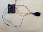
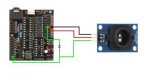
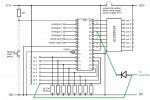
As a continuation of assisting forum member tonyg with using the Parallax ColorPAL colour sensor and colour generator module,
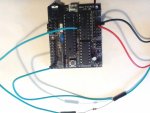
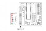
I have prepared the attached tutorial which may help others with the required hardware connections and basic PICAXE programming
to use the ColorPAL module.
Access to a ColorPAL module was courtesy of tonyg and The Hex to Decimal subroutine in the program examples is unashamedly one written recently by hippy.
 

Attachments

Last edited:

rhampton

New Member
I hope it's ok to resurrect this thread rather than starting a new one. Fantastic detail in the tutorial but I'm having some trouble. My daughter and I are working on a color sorter for a science project. We're using a Picaxe-28X1 (AXE020) and the ColorPal. I am testing my setup with the code at "7.3 Simple program for M or X1 PICAXE". So far after download I am getting no response in the PE terminal.

picaxe_colorpal.jpg

Two questions: am I connecting to the correct ports? Is there a specific diode I should use? I'm not at all familiar with diodes and found that RadioShack has a few hundred to choose from. I have tried both of these at the suggestion of the less-than-helpful RS clerk:

http://www.radioshack.com/product/index.jsp?productId=2062589
http://www.radioshack.com/product/index.jsp?productId=2062576

Any help is appreciated. Thanks!
 

Attachments

Technical

Technical Support
Staff member
Welcome to the forum.

Wrong connection points on the project board - you are connected to the 'buffered' open-collector outputs.
You need to connect to the row of the holes between the two chips - which is then a straight connection to the PICAXE pins.
 

rhampton

New Member
Welcome to the forum.

Wrong connection points on the project board - you are connected to the 'buffered' open-collector outputs.
You need to connect to the row of the holes between the two chips - which is then a straight connection to the PICAXE pins.
Thank you. So both 3 & 7 need to be in that middle row?
 

westaust55

Moderator
AXE020 with ColorPAL

Thank you. So both 3 & 7 need to be in that middle row?
No, with reference to your photo/image, the green wire to the bottom left stays as shown. Only the green wire to the ULN2803 at right side must be moved to the point between the two chips.

See the attached marked-up AXE020 schematic.

Two reasons for the need to move the wire:
1. As Technical mentions, the ULN2803 outputs are open collector, so nothing to pull the signal high - unless you add a pull-up resistor
2. The ULN2803 inverts the PICAXE output signal so the ColorPAL would not recognise the signals/data - unless you also invert the mode (iNverted versus True) for the SEROUT command.
 

Attachments

rhampton

New Member
No, with reference to your photo/image, the green wire to the bottom left stays as shown. Only the green wire to the ULN2803 at right side must be moved to the point between the two chips.

See the attached marked-up AXE020 schematic.

Two reasons for the need to move the wire:
1. As Technical mentions, the ULN2803 outputs are open collector, so nothing to pull the signal high - unless you add a pull-up resistor
2. The ULN2803 inverts the PICAXE output signal so the ColorPAL would not recognise the signals/data - unless you also invert the mode (iNverted versus True) for the SEROUT command.
Got it. Any suggestions on the diode? I've tried your test routine as well:

SYMBOL sinp = 7
SYMBOL sipp = pin7
SYMBOL sout = 3

CP_Reset:
LOW sout
HIGH sout
DO UNTIL sipp = 1 : LOOP
LOW sout
PAUSE 80
HIGH sout
PAUSE 10
RETURN

If I understand it sending "= R !" from the PE terminal window I should turn on the red LED. Instead I get back "ðððððððððððððððððððððððððððððððððððððððððððððððððððððððððððððððð¥¦ðððððððððððððððððððððððððððððððððððððððððððððððððððððððððððððððð¥¦" and no red LED. The diode is the only thing I can think of that I might have wrong.

Thanks!
 

westaust55

Moderator
For the diode, the second link you gave for the 1N914 signal diode would be the better selection.
Do you have the diode the correct way? The end with the band needs to be towards the PICAXE Output pin.

Yes, after the ColorPAL is reset/initialised, sending "R!" should turn on the red LED.
But it will only turn on the Red LED. you would need to send additional commands to initiate the taking of a sample of light levels

If you are sending R! from the PE then your PICAXE code will be different to the example I have provided to get folks going.
Can I suggest that you try the PICAXE X1 example code I have provided first and then, when you have some valid activity then move on the adding comms from the PC and the PICAXE.
See if you can get the Version number returned first to verify that you have valid comms occuring.

If still no luck, then post a photo of your project taken perpendicular (not slanted) and clearly showing each end of each wire so folks can trace through the circuit to verify if the wiring is right.
 

hippy

Technical Support
Staff member
If I understand it sending "= R !" from the PE terminal window I should turn on the red LED. Instead I get back "ðððððððððððððððððððððððððððððððððððððððððððððððððððððððððððððððð¥¦ðððððððððððððððððððððððððððððððððððððððððððððððððððððððððððððððð¥¦" and no red LED. The diode is the only thing I can think of that I might have wrong.
Not sure what you're really trying to do, how you have things wired or what PICAXE program you are using, but what you see on the Terminal display is typical of the 'garbage' received from the PICAXE when sending data to the download serial in.

Seems you have your cable connected to the PICAXE not the ColorPAL sensor.
 

rhampton

New Member
For the diode, the second link you gave for the 1N914 signal diode would be the better selection.
Do you have the diode the correct way? The end with the band needs to be towards the PICAXE Output pin.

Yes, after the ColorPAL is reset/initialised, sending "R!" should turn on the red LED.
But it will only turn on the Red LED. you would need to send additional commands to initiate the taking of a sample of light levels

If you are sending R! from the PE then your PICAXE code will be different to the example I have provided to get folks going.
Can I suggest that you try the PICAXE X1 example code I have provided first and then, when you have some valid activity then move on the adding comms from the PC and the PICAXE.
See if you can get the Version number returned first to verify that you have valid comms occuring.

If still no luck, then post a photo of your project taken perpendicular (not slanted) and clearly showing each end of each wire so folks can trace through the circuit to verify if the wiring is right.

I am using the example code at "7.3 Simple program for M or X1 PICAXE". I have tested all of the wires with other i/o devices to ensure they are not broken, including signal and direction through the diode. Below is an image of my project. Hopefully someone can find something wrong because this is driving me crazy. I'm by no means an expert but this shouldn't be so difficult! :)

Thanks again!
 

eclectic

Moderator
Suggestion.

Bend the wires so that they are closer to the board.

Then, zoom in and take a higher resolution shot.

e
 

westaust55

Moderator
Sorry, nothing comes to mind at this time.
If the circuit is correct which form your photo and your PICAXE input clarification it seems to be and the code is as per my getting started tutorial then, other than a faulty ColorPAL, I am at a loss for suggestions.
I presume that you do not get a version number return when you run the code form the tutorial ???
what voltage are you operating the circuit at?
 

hippy

Technical Support
Staff member
I'm about ready to give this thing up! Any other suggestions, guys?
Perhaps a recap on where you are, which code you are using and particularly photos of how you have your circuit board wired up now may entice people to take a look at it again.
 

westaust55

Moderator
Using the Parallax ColorPAL Colour Sensor module with PICAXE chips - A 14M2 solution

It has been identified that the programs as presented for the 40X1 and 18M2 will not function on some other parts such as the 14M2 and 28X2.

Tests today with a 14M2 reveal that the problem is when running at 8 MHz clock speed the transition from SEROUT to SERIN is not fast enough at 8 MHz.
The solution for the M2 parts is to operate at 16 MHz (or faster).

Attached is a revised program which works on the 14M2.

See next post for the 28X2 solution (page 3 of this thread)
 

Attachments

Last edited:

westaust55

Moderator
Using the Parallax ColorPAL Colour Sensor module with PICAXE chips - A 2 solution

Tests today with a 28X2 reveal that the problem is when running at 8 MHz clock speed the transition from SEROUT to SERIN is not fast enough at 8 MHz.
The solution for the X2 parts is to operate at 16 MHz (or faster).
with an AXE091 Development board and onboard 8 MHz resonator it will be necessary to operate at 32 MHz (4 x 8 = 32)

Attached is a revised program which is operating on the 28X2 at 32 MHz.
 

Attachments

crane.ep

New Member
Hi all! I'm fairly new to the Picaxe and basic programming. My background is primarily in PLC and Ladder. I'm trying to make a color sorter and have decided on a ColorPAL and Picaxe 28x2. I stumbled upon Westhaus55's code after a bit of searching on how to communicate with the ColorPAL.

I've run into a bit of a problem and I'm completely out of ideas on how to proceed. I can't get the ColorPAL to respond at all. Problem is I don't know if it's something I'm doing or if it's the code or something else.

At first I had the CP wired with +5 to +5vdc, gnd to the same gnd as my picaxe, and data to the c.0 (28x8 pin 11). Programmed the pic with the 28x8 program from westhaus55 and nothing happened. No flashing lights, no serial monitor, nothing. I ran a simulation and the serial monitor popped up, the program got to the point where it waits for CP to drive c.0 and stopped. I clicked c.0 in the simulation window and the program continued.

I then read that the 28x2 needed at least an 8mhz resonator to function fast enough. Instead of buying a resonator I just picked up the axe201 which has a 28x8 and 16mhz res on board. Hoping that would fix the issue I programmed it. Still nothing.

I then wired up an NPN transistor with c.0 to the gate, CP data to the collector and emitter to ground. Again nothing.
Tried with an N channel MOSFET. Still nothing.
Hoping maybe AXEpad would have a live simulation feature so that I could watch the program execute in real time to see where it was hanging up I went through the hassle of installing LinAXEpad on my Ubuntu machine and programmed the chip. Turns out AXEpad doesn't have a live simulation feature. Neither does Picaxe programmer 5.

I tried it with my Arduino and some ColorPAL demo software I copy/pasted. Nothing.

I don't know if I somehow fried it or it was bum out of the box. I've gotten a flicker on the led hear and there but that's it. Is there a test program I can run to just check the leds? At this point I just want to make sure it works.

Any help I can get will be incredibly helpful. Thanks
 

westaust55

Moderator
Sorry for the delay in responding.

Programmed the pic with the 28x8 program from westhaus55 and nothing happened. No flashing lights, no serial monitor, nothing.
Having a #TERMINAL directive/instruction only opens the PE Terminal Window following a program download, not when you power down and restart at a later time.
The better option is to press the "F8" function key which will open the PE Terminal WIndows (works in both PE5 and PE6).

I then wired up an NPN transistor with c.0 to the gate, CP data to the collector and emitter to ground. Again nothing.
Tried with an N channel MOSFET. Still nothing.
Adding a transistor will invert the signal to the ColorPAL and block the return signal and thus would not work.
You should only need to connect the PICAXE C.0 pin directly to the ColorPAL data pin.

IF it is all connected correctly and communicating you should at least see
firstly the message "Getting ColorPAL Version. . ."
then the message "ColorPAL Version = " followed by the ColorPAL version number as the GetVersn subroutine is call immediately after a ColorPAL reset.
Code:
GetVersn:
 SERTXD ("Getting ColorPAL Version. . .", cr, lf, cr, lf)
  SEROUT sio, T4800_32, ("= v !")
  SERIN  sio, T4800_32, temp1, temp2
  SERTXD ("ColorPAL Version = ", temp1, temp2, cr, lf, cr, lf)
  pause 1000
  RETURN
 
Top