Picaxe , Load cells and Op amps

jkrehrer

New Member
Hello,
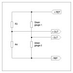
My name is Jim and I'm new to the pic axe(I have a 20M2). I got myself involved in a project for school using a Pic axe and am having some trouble understanding whats happening. My main goal is to make an auto bottle filling machine using two load cells. I have the load cells connected to a two stage op amp set up that is giving me around a 2 volt output w/o load...and goes up from there, but stays below 5v when at desired weight. Everything seems OK on the op amp side of things. The problem is when I put the Op amp output into the Pic. The extent of my program is to just Debug at this point to make sure the Pic is reading OK. When I do this the resolution displayed (and voltage read from Pic input) Is way higher then before I connected to pic...sometimes over 5v and maxes out the resolution at 255...and even when not maxed out to jumps around quite a bit...again I am new to this and somewhat new to electronics....one thought I was having was a problem with commons? But anyway I see it I am somehow getting voltage FROM somewhere when the pic is connected to op amp output. I guess what Im looking for is suggestion, or any insight anyone might have for this application. If I left out any inportant piece of info let me know and Ill try to answer.
 

Bill.b

Senior Member
Hi Jim

Could you provide a schematic (circuit) of then opamps and the connection to the 20m2 and the code you are using in the picaxe.
this would help us determine the problem and give you the correct advice.

Regards

Bill
 

Billo

Senior Member
Can you provide a schematic of how things are hooked up? A photo would be helpful too.

It does sound to me like a grounding issue.
 

jkrehrer

New Member
thanks for the replies guys, ill try to answer a little before bed. I have the load cells powered from 5v off of an old computer power supply. the op amp is powered off of two 9v batteries in series, with the "common" being the center tap of the series connection. all "commons or grounds" on the op amp schmatics are tied to this point. the out put from the op amp goes to the pic pin C1 on my Pic which is powered from my laptop usb on a breadboard.
the only programming I have done so far with this is with Logicator converted to basic...

'BASIC converted from Logicator for PICAXE flowsheet:
'C:\Users\Melissa\Documents\debug.plf
'Converted on 12/3/2012 at 21:47:52

symbol varA = b0
symbol varB = b1
symbol varC = b2
symbol varD = b3
symbol varE = b4
symbol varF = b5
symbol varG = b6
symbol varH = b7
symbol varI = b14
symbol varJ = b15
symbol varK = b16
symbol varL = b17
symbol varM = b18
symbol varN = b19
symbol varO = b20
symbol varP = b21
symbol varQ = b22
symbol varR = b23
symbol varS = b24
symbol varT = b25
symbol timer = time


let dirsB = %11111111


main:
label_2: readadc 1,varA
debug
goto label_2


#no_data 'reduce download time

Again I think its a referencing problem that I am not getting and trying to understand....should I be powering the load cells off of the USB? When I take readings I use the center taped "common" off of the 9v batteries as my neg. and output from op amp as positive....
 

SAborn

Senior Member
Im confused??? (nothing new there) so you have 3 power sources, 1 psu to the load cell, 1 battery supply to the opamps, and a usb supply to the picaxe, is this correct?

Sounds like a nightmare for ground loop problems, are ALL the negatives connected together to form a common ground as the problem you have would imply this is not the case.

It would be far better to use a opamp designed for single rail supply and do away with the +/- power supply need, then the whole circuit can be supplied from a single power source.
 

BeanieBots

Moderator
Your description sounds OK but without a circuit it will be almost impossible for us to help.
Your op-amp output is OK, so leave that part alone.
Try testing your PICAXE input with a potentiometer connected between PICAXE 0v and 5v with wiper to input. (use a 10k pot).
 

Jeremy Harris

Senior Member
I've got a fair bit of experience with using strain gauges (the active components in load cells) and, unless your load cells have built-in signal conditioning then I don't think you're going to have much luck with getting a reasonable result with ordinary op amps. The signal level from even a full bridge load cell is tiny, down in the input noise and offset voltage drift range for a standard op amp. If the load cells are half bridge, which is fairly common in cheaper ones, then the noise and offset problem is twice as bad.

I use half bridge load cells made from bonded film strain gauges and single rail instrumentation amps, usually the excellent INA122. This will run from a single 5 V rail and makes interfacing to the Picaxe easy, as with good supply filtering it can share the Picaxe 5 V rail.

Noise and drift are potential problems that need to be carefully addressed at the analogue end. If your load cells are half bridge, then the fixed resistor half bridge used to get the offset voltage has to be made using low noise (metal film) resistors that have a similar temperature coefficient to the strain gauges in the load cells. Often you will need to trim the offset by adding high value parallel resistors across one or the other of the fixed half bridge resistors, as even 1% tolerance resistors aren't accurate enough to get a good zero.

The instrumentation amplifier will need a fair bit of gain, probably around 100 depending on the load cell output. Even a low noise amplifier like the INA122 will get noisy at high gains, so if you can cope with a slower response time then adding an RC filter on the output will help reduce the problems at the Picaxe analogue input by averaging the higher frequency noise.

Connecting to the Picaxe should be easy enough, but as has been pointed out you need to avoid earth loops and make sure that there is a single ground connection from the load cell and amplifier to the Picaxe circuit, with the power supply ground being connected to the Picaxe side. Even with a good set up and an instrumentation amplifier you can expect some digital noise on the Picaxe A/D reading. Bear in mind that a single bit (assuming a 5 V power supply and 10 bit ADC) is less than 5 mV at the Picaxe input, which with an amplifier gain of 100 would be less than 50 uV at the load cell, a very tiny signal indeed.

Finally, I agree with the calls above to see a circuit, it will help immensely to see what you're doing. Your system can be made to work OK, I'm sure, but may need some better circuitry at the front end to get reliable signals into the Picaxe.
 

jkrehrer

New Member
OK So I tried to make a schematic with the program that was linked (thank you!) I have also ordered some ad620an instrimental op amps to try. Any idea how they compare to the INA122?

For now I would like to try to get the op amps I have to work for school. After this project is over for school I am going to make it totally a Picaxe operation with Instrimental op amps, but for now it is just used with a discrete only input PLC as an ADC, and the PLC doing most of the work.


boriz

Senior Member
"My main goal is to make an auto bottle filling machine using two load cells."

It has to be load cells?

Why two?
 

sghioto

Senior Member
If the schematic is correct then the problem is the USB- on leg 20 of the 20M2. This needs to be connected to all the common grounds as first suggested by Saborn.

Steve G
 

Jeremy Harris

Senior Member
The load cell schematic seems to be unusual, as normally the elements would be connected as a bridge. It looks like you have a common half bridge load cell, with two fixed resistors (R3 and R4) acting as the dummy bridge elements. These need to be extremely accurately matched; as I mentioned before, even 1% tolerance resistors won't be accurate enough to get a good zero on the bridge. The bridge connections for a half bridge load cell should look like those below: strain gauge load cell - half bridge.jpg

The reference voltage (the difference between +REF and -REF on the diagram) needs to be stable and accurate, as any change in this voltage will change the sensitivity of the load cell, throwing the readings off. It's normal to use a fairly accurately regulated power supply for the load cell reference to maintain reasonable accuracy.

The load cell output is from the centre tap of the active elements of the bridge (the junction between the two strain gauges). The dummy half bridge resistors, R3 and R4 in your diagram and mine, supply a zero reference voltage to the differential amplifier that's needed to process the signal. The values of R3 and R4 need to be adjusted so that the voltage at their junction exactly (to within a few tens of microvolts!) matches the voltage at the junction of the strain gauges with no load applied. This sets zero and ensure that the output is zero with no load applied, any offset here will move the zero and reduce the dynamic range of the load cell. The two dummy resistors need to have temperature coefficients that are close to that for the strain gauge material. Usually metal film resistors are a fairly close match. Adding a zero adjustment pot on the dummy bridge works OK to set zero, but will introduce a temperature dependent zero shift, meaning that zero may need to be re-adjusted if the temperature changes.

The instrumentation amp doesn't need to be anything very complex and the AD620 can be used OK, but it is intended for dual supply operation, making it a little more awkward to run from a single rail than the INA122. You need to configure the amplifier as a true differential amplifier, with the inputs (+ and -) being connected to the two sides of the bridge. Using a single-sided amplifier, as you are at the moment, will result in a lot of drift, as you're trying to amplifier a very tiny signal.

Do you have any data for the load cell? Usually there is a figure that gives the output voltage for a given reference voltage and load. Knowing this I could quickly let you know how much gain you need to get a good range on the Picaxe ADC input.

EDITED TO ADD:

I've just dug out the schematic for a very simple, non-critical, load cell amplifier I made a while ago that may help. This used aluminium strain gauges that were 120 ohm, rather than the higher resistance constantan strain gauges that I think your load cell uses, so the 100 ohm half bridge resistors I'm using would need to be changed for maybe 270 ohm ones to match your load cell and give a reasonably good input resistance match for the amplifier. This amplifier has a zero adjustment pot, a ten turn wire wound pot that wasn't too unstable with temperature (although it did drift a bit). The pot on the output was needed to set the gain, as this amplifier drove a digital meter directly, rather than a Picaxe. In use the zero was adjusted as needed before any measurement was made, something that might not be needed for a rough "go - no go" type of measurement.
 

Attachments

Last edited:

SAborn

Senior Member
A little bit of thermal drift can always be tared out in the picaxe, by just using a button to read the adc with no load and set that as a zero point, although the better the circuit the less frequent it is needed to tare the reading.

I personally would not mess with using an opamp at all and use the ADS1231 chip made for bridge sensors, its a wonderful 24 bit device and easy to use. (but its SMD)

Jeremy's circuits look to be simple and well tested, i will let him guide you.
 

jkrehrer

New Member
Thanks for the Replies everyone!
first, the reason I have 2 load cells is because it will be a 2 station filling machine.
Second. I guess I misrepresented what I think I have. I think my cells are a full bridge, I didnt know how to draw them in correctly with the schematic program yet, but I will provide the info I have which isnt much
Load Cells
http://www.ebay.com/itm/220406510358?ssPageName=STRK:MEWNX:IT&_trksid=p3984.m1497.l2649

This is the PIC setup I have.
http://www.ebay.com/itm/200655981871?ssPageName=STRK:MEWNX:IT&_trksid=p3984.m1497.l2648
 

SAborn

Senior Member
You would just draw the load cell bridge the same as a bridge rectifier but use resistors instead of diodes. (Clue "Bridge")
 

Jeremy Harris

Senior Member
They may be full bridge, but my guess is that they are half bridge with two dummy strain gauges bonded on at right angles to make up the other half of the bridge, as bending beam cells like this are often a bit awkward to assemble as full bridge units. Anyway, the data is all there to get an amp working properly. The load cell puts out 2 mV per volt of applied bridge voltage (the total voltage across the reference or excitation connections) when the cell is at the full load of 5 kgf. If you used a 5 V supply for the excitation voltage, then you would get a 10 mV voltage difference between the output wires when the load cell was loaded with 5 kgf. With no load applied the load cell would have a zero offset of 2% of 10 mV, or 200 µV.

If you want the full 5 kgf to give an output of about 5 V, so that you can get the maximum resolution from the Picaxe analogue to digital converter, then you need an amplifier gain of 5 / 0.01 = 500. A gain setting resistor, Rg, with a value of 100 R will give you a gain of 495 on the AD620, which will be about right. Page 14 of the AD620 data sheet (here: http://www.analog.com/static/imported-files/data_sheets/AD620.pdf) shows a pressure sensor application that is near-identical to your requirement. Ignore the AD705 bit and connect the REF pin of the AD620 (pin 5) to a reference voltage.
 

RadioBob

New Member
Your PicAxe will read 0 for 0 volts, and 255 for a voltage equal to the positive supply. You have to scale the reading if you wish it in volts. Try dividing your reading by 51 if you are using a 5 volt supply.
 

SAborn

Senior Member
It would be foolish to only read to 255 for a load cell, when 10 bit resolution will give 0 to 1024, much more head room to work with. (readadc10)

The scaling would be in a weight form like Kgs or LBs not in volts, its not a lot of use displaying a bottle filled with 200 volts?
 

jkrehrer

New Member
UPDATE*
Just wanted to thank everyone for their help! I got some INA 122's instead of the others and they worked great! Im still working out some bugs with programming between the PLC and PIC but we are not far off from getting done!!
Again Thanks!!
Jim
 
Top