Latching Circuit

TinkerJim

Member
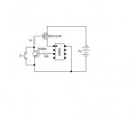
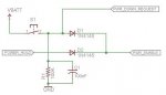
The following circuit was intended to switch on a Picaxe through a p-channel Mosfet by momentarily depressing a button.

Picaxe Latching Circuit.jpg

The first step of the program is "Low 4" which then keeps power on (the gate of the Mosfet being held low). That part works fine.

After the program runs down to its next to the last step, it was supposed to turn itself off by making the gate pin high as its last step.
Then no energy would be consumed until the momentary switch was depressed. But that part doesn't work as intended!

After the program executes the final line (High 4) current falls not to zero, but about 15 uA. And this is the exact same current draw that the 08M2 draws when powered directly from the battery and sitting idle (i.e. finished running a program)

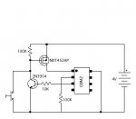
Also tried a 100K pull up to the gate. And also tried an n-channel on the other side of the MC. No luck.

Any help would be appreciated.
 

darb1972

Senior Member
Hello Jim

I am no expert at Picaxe, but know a thing or two about electronics. I don't think what you trying to do will work for several reasons. Firstly, the FET will only be (technically) switched on for the duration of the switch depression. This also doesn't take into account the very unstable voltage/s created by pressing and releasing a switch (eg: switch contact bounce). The most likely reason the Picaxe would remain on is because it can operate on tiny current AND regardless of how much you try to bias off the FET, there will always be "leakage" in the form of resistances (probably more so with a FET). No component is perfect. Leakage, stray capacitance etc will always exist. With regards to leakage, whenever a potential difference exists then current (often tiny current) will flow. This might explain the issue.

With regards to your design, may I suggest you make some simple changes? If it were me, I would remove the FET completely and only add a resistor/capacitor across the switch to reduce switch bounce (or build this into your code). When the switch is pressed you could possibly put the Picaxe into a sleep mode. The only issue would be waking it up again. I cannot redraw a circuit at the moment (on a mobile device) but I can do this later if needed.

I am not sure I entirely understand what you are trying to achieve here so I hope my suggestions are helpful.
 

nick12ab

Senior Member
If you need a self-switching circuit, then how about this? You'll need a thyristor instead of a MOSFET.

Don't forget to pull the serial in pin down to 0V.

@tinkerjim, what is your application? Providing this information often results in getting better solutions from the experts.
 

beb101

Senior Member
I have been looking into powering on a 20X2 after a Sleep 0 and came across a circuit from here,

http://electronics.stackexchange.com/questions/25948/how-to-improve-this-power-on-off-circuit

Its explanation,
Quote:
"Pressing the button with power off enables PWR_ENABLE turning on the micro (or power supply or whatever). The micro asserts POWER_HOLD to keep the power on. The micro then monitors PWR_DOWN_REQUEST to see when the user has pressed the button again. If VBATT is above the level that can be fed into an input of the micro, a voltage divider can be added."

Regards,

Baxter
 

Attachments

darb1972

Senior Member
@ Nick

Not a bad idea. Only one main concern I would tend to consider when using such a design. When the SCR is, even at low current, it will have a "forward on" voltage. According to the spec sheet for one of the suggested devices (106D), the forward voltage could be as much as 2.2V, however this is at 4 amps.

Given that this is at much lower current, I would tend to suggest a much lower forward voltage, maybe something around 0.6V to 1V (speculative guess). This would result in an output from the voltage regulator of around 5.6V to 6V. Probably worth throwing in a diode on the output to drop about 0.6V off the Vcc to protect the Picaxe.

Also worth noting that although the "latch current" is around 5mA, the "hold current" is around 3mA. Depending on circuit design and Picaxe function/s, I would tend to suggest that the Picaxe runs and LED off an output to ensure the system current doesn't fall below the hold current prior to putting the Picaxe to sleep. The LED would need to be off the Picaxe, otherwise the circuit would never switch off.

Anyway, that's just a few more thoughts on the matter. Good concept though.
 

Dippy

Moderator
I'm afraid circuit No.1 won't work. It's like trying to lift yourself off the ground by pulling your foot.

You can do it with an enable-able regulator or thyristor or simply use 2 transistors.
Using MOSFETs will give the lowest power.
It has been done several times here over the years.

I did a circuit with 18X years ago with 2 MOSFETs with a PP3 9V alkaline.
The reason I did it like that was that the MOSFET switching was upstream of the regulator and so minimised power.
I've just got it out of the drawer and it still works after 4 years- yes, the same battery :)
(Satan hates PP3s, but in the right place/app they are perfect :) .)
 

sghioto

Senior Member
Probably too late but this is the fix if you decide to keep the circuit as is.
And change "LOW 4" to "HIGH 4"
Cheers,Steve Glatching 08M2.JPG
 

KMoffett

Senior Member
Thanks, Steve ! I'll try it.
There may be a problem with leaving the gate floating in the un-powered state. You might want get rid of the 1K resistor, stick a 100k resistor between the gate and source and connect the collector directly to the gate. Maybe, also put a 100K resistor from base to emitter.
Ken
 

TinkerJim

Member
There may be a problem with leaving the gate floating in the un-powered state. You might want get rid of the 1K resistor, stick a 100k resistor between the gate and source and connect the collector directly to the gate. Maybe, also put a 100K resistor from base to emitter.
Ken
Yes, KMoffett, I neglected to show a 100K pull up resistor on the gate in my initial diagram (there was also a 100K pull down on Pin 2 of course that I didn't show). And, yes, a pull down on the base of the transistor might be needed. I'm going into the shop now...
 

TinkerJim

Member
Your suggested circuit works perfectly Steve!
Here is the schematic as I tested it.
Working Picaxe Latch.JPG
First step in the program is "High 4" and the last one is "Low 4"
It turns on with a touch of the button switch, keeps itself on, and after running through its program, it turns itself off completely.
Thanks very much !

Jim
 

KMoffett

Senior Member
Your suggested circuit works perfectly Steve!
Here is the schematic as I tested it.
View attachment 10674
First step in the program is "High 4" and the last one is "Low 4"
It turns on with a touch of the button switch, keeps itself on, and after running through its program, it turns itself off completely.
Thanks very much !

Jim
I see you have a 100K to Pin2, which is good too, but would still recommend a 100K from either the base to ground or pin 3 to ground.
Ken
 
Top