Thermocouples made really easy

matherp

Senior Member
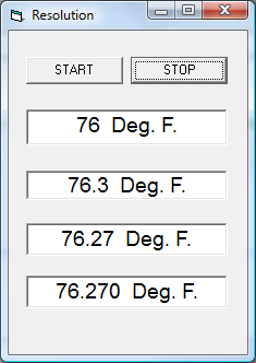
Thermocouple conversion comes up so often that I decided to tidy up some code I'd previously developed in the hope it is useful. This uses a Type K thermocouple and works from 0-999 degrees C. The program as written gives 1 degree resolution throughout the range but with some easy interpolation could give 0.2 degrees. Accuracy will depend on the quality of the thermocouple, wiring, board layout etc, but should be pretty good. All data for conversion is held in an external EEPROM so the main program doesn't use any precious table space or onboard EEPROM. Conversion speed is too fast to time and certainly quicker than the ADC.

I use a MCP342x series ADC to read the thermocouple voltage direct. The ADC has an internal 8x gain pre-amplifier which in 16 bit mode gives 5-6 ADC counts per degree. It must be used in this mode to match the conversion tables provided.

To make the conversion easy I've programmed up an EEPROM with ADC values from 0-999 degrees C. I use a DS18B20 to read the cold junction temperature. This must be placed in the same location as the joints between the thermocouple wires and the copper wiring to the ADC.

So the complete circuit is an I2C capable picaxe, a EEPROM (min 16KB), a MCP342x series ADC which in the case of the MCP3424 can read 4 channels, and a DS18B20. To program the EEPROM (a one off activity) you will need a I2C capable picaxe with 4096 bytes of program memory.

The example conversion program below uses just 239 bytes of memory so could be run on a 08M2.
Code:
'
' Type K thermocouple measurement using a picaxe, a 16kb eeprom and a MCP342x series ADC
'
#picaxe 28x2
symbol scratch=b25
symbol scratch1=b26
symbol wordlow0 = b0
symbol wordhigh0 = b1
symbol coldjunction=b2
symbol cjconvert=w10
symbol cjconvertlow=b20
symbol cjconverthigh=b21
symbol typek=w11
symbol typeklow=b22
symbol typekhigh=b23
symbol ADCreading=w12
'
' ADC constants
'
symbol ADC = %11011000 ' set to match your hardware, NB base address is same as DS1307
symbol Chan0= %10000000
symbol Chan1= %10100000
symbol Chan2= %11000000
symbol Chan3= %11100000
symbol Gain1=%00000000
symbol Gain2=%00000001
symbol Gain4=%00000010
symbol Gain8=%00000011
symbol Bits12=%00000000
symbol Bits14=%00000100
symbol Bits16=%00001000
symbol ADCtimeout=5' tune the timeout if using faster clock speeds
'
symbol SEEPROM =%10100000
symbol cjtableoffset=$3000
'
gosub I2Cclear' routine to clear jammed i2c bus if system is reset while slave write is ongoing
'
hi2csetup i2cmaster, ADC, i2cslow, i2cbyte 'NB we are going to have to handle the word addressed eeprom in byte mode to match the MCP3424
'
do
'
'
	readtemp A.1,coldjunction
	if coldjunction>127 then: coldjunction=0:endif 'don't allow a negative cold junction temperature
	w0=coldjunction*2+cjtableoffset 'convert to the word address of the lookup table in the EEPROM
'
	hi2cout [SEEPROM],(wordhigh0,wordlow0) 'send out the word address
	hi2cin [SEEPROM],(cjconverthigh,cjconvertlow)' read in the equivalent thermocouple ADC reading
'
	b0= CHAN0 | Gain8 | Bits16 'Must be gain 8 and Bits16 for thermocouple conversion
	gosub rADC 'returns reading in w0
'
	ADCreading = w0 ' save for printout
	w0=w0+cjconvert 'add the cold junction equivalent reading into the thermocouple value
	w0=w0*2 ' convert to a word address for lookup in the EEPROM
'
	hi2cout [SEEPROM],(wordhigh0,wordlow0)
	hi2cin [SEEPROM],(typekhigh,typeklow)
'
	sertxd ("Coldjunction: ",#coldjunction," ADC equivalent: ",#cjconvert," ADC reading: ",#ADCreading," Temperature: ",#typek,cr,lf)
'
	pause 1000
loop		
'


rADC:

' read thermocouple with parameters defined in b0
'
	hi2cout [ADC],(b0) 
	scratch1=ADCtimeout ' tune the timeout if using faster clock speeds
waitADC1:
	pause 75
	hi2cin [ADC],(wordhigh0,wordlow0,scratch)
	scratch =scratch & %10000000
	dec scratch1
	if scratch != 0 and scratch1 !=0 then waitADC1
	if scratch1 <>0 then
	' successful conversion do any local processing here if required	
	else
	' error condition here if required
	endif
return
'
' clear the i2c bus if jammed
'
I2Cclear:
	input c.4
	output c.3
	high c.3
	do while pinc.4=0 
		low c.3
		pause 50
		high c.3
                pause 50
	loop
return
There is direct table lookup for both the thermocouple conversion and the coldjunction compensation - no maths required!

The magic is in the contents of the EEPROM. The load program is:

View attachment eepromload.bas

This programs the EEPROM and does a sanity check to make sure all is OK. It takes about 5 minutes to run.

If you want a MCP3424 ready mounted to play with you can get them from various sources but I've had success with Jeelabs (just ignore their bizarre labelling of the I2C signals)

Hope this is useful

Best regards

Peter
 
Last edited:

premelec

Senior Member
Hi - thanks for this ! perhaps put it in finished projects - and if you've worked out numbers for other thermocouple types please post those too.
 

mrburnette

Senior Member
I have used thermo couples... but they are not my friends and do not lead to simple, inexpensive designs. They have their place, however.

The IR sensor is non-contact, factory calibrated, digital, and includes instrument ion amp and eeprom.
Here is some PICAXE demo code http://www.phanderson.com/picaxe/mlx90614.html

At under $17 U.S. these make for a simple and robust high quality and high accuracy thermometer. Just have a good read on emissivity before ordering the device to understand potential constraints...
http://www.optotherm.com/emiss-table.htm

- Ray

Working demo: http://www.instructables.com/id/LASER-HEAT/
 

Goeytex

Senior Member
Thermocouples certainly do have their place and it it a huge one where non contact
IR Sensors are not even considered. Thermocouples are generally indicated when measuring
relatively high temperatures and/or there needs to be fast response, such as measuring the
temperature the exhaust gas of of internal combustion engine, or the air temperature inside
an industrial oven. I doubt a non contact IR sensor would fare well underwater measuring
the temperature of seawater at 20 fathoms.
 

mrburnette

Senior Member
I doubt a non contact IR sensor would fare well underwater measuring
the temperature of seawater at 20 fathoms.
History indicates that before the thermocouple use, Pyrometers were used... I will not bore you, it is a good Wiki read.

An IR sensor will work perfectly well underwater assuming the casing was 'waterproof' ... just because there is no human-visible light does not mean that there is no electromagnetic energy in the optical spectrum. The issue one must consider underwater is the exposure of the coated optical window to seawater since the common design is to interface with air; I suspect a different coating would be utilized for a quartz-water interface to optimize IR transmittance. Any optical engineers out here?

- Ray
 

Dippy

Moderator
Each sensor has it's place.
IR thermometry requires care because the target emissivity needs to be taken into account.
 

techElder

Well-known member
Whoa! I gotta go get my high top boots if this thread goes any further!

"quartz-water interface to optimize IR transmittance" "IR thermometry" "target emissivity" "temperature of seawater at 20 fathoms"
 

Dippy

Moderator
What are these high top boots?
Are they these kinky thigh-length boots?

You realise that image is going to put some people into therapy? :)
 

Reloadron

Senior Member
Each sensor has it's place.
IR thermometry requires care because the target emissivity needs to be taken into account.
I measured temperature once, well OK, maybe twice. I believe Dippy covered it quite well in five words. Each sensor has its place would seem to cover it quite well. When choosing a sensor and method to measure temperature all of the variables need to be considered and only then a decision made.

Just My Take...

Also, many thanks to matherp for sharing some very informative and useful information, especially in overcoming the CJC when using a thermocouple with a PIC.

Ron
 

John West

Senior Member
I have three requirements for my general purpose temp sensors - that they be inexpensive, because I'm cheap, and sometimes wish to measure several different spots, that they be convenient to use in degrees F (as I live in the USA,) and that they measure down to -40 degrees or so, as I find myself measuring cold more often than heat.
 

mrburnette

Senior Member
Each sensor has it's place.
IR thermometry requires care because the target emissivity needs to be taken into account.
Precisely what I said:
They have their place, however.
and

I gave a URL to a table of common emissivity for the benefit of a quick-reference, although there are far more complete tables available.
IR thermometry requires care because the target emissivity needs to be taken into account.
Certainly, I was not in attack-mode going for matherp's jugular; I am in appreciation of the information presented in the opening thread... having one IC to manage the instrumentation amp, cold junction, and linearity is great information. The eeprom code is a particularly nice addition, too. It may have seemed that I was attempting to capture the thread on thermocouples and redirect to IR temperature, however, my true ambition was simply to state that other technologies exist and that unless one is building a project for educational purposes to study thermocouples that consideration should be given to some serious pre-project exploration of technologies to pick the appropriate one.

However, my opinion was only to state the obvious and provide a cost-effective, accurate, robust alternative which can be implemented in a 20X2 with the addition of 2 resistors and the MLX90614... all for under $20 U.S. In retrospect, this does seem a little terse and maybe even disrespectful... nothing could be further from the truth.

Two different approaches, two different cost-benefit ratios, two different component counts... similar accuracy (0.02C) within the confines of the working range. I do, however, apologize for my failure to note for the lay-persons who read our musings that there are various technical approaches to temperature measurement and in such stating I should have made a reference to the "Technologies" heading under this URL: http://en.wikipedia.org/wiki/Temperature_measurement ... such was my oversight.

For those considering any temperature measurement projects, give a little research into the technologies used and the products available... you may find that a $0.10 thermistor and $0.05 precision resistor and a little software is all that is necessary to accomplish 0.5F (or better) readings.

- Ray
 

Dippy

Moderator
Aw, don't feel ignored MrBurnette.... we were listening.:)
Echoes happen a lot. I didn't post to 'out-do' you or steal your thunder.

When you said "They have their place, however. " you were speaking about thermocouples, I was speaking about ALL types of sensor.
I know advice here can often be, shall we say, 'competitive' which is quite amusing ;)

Anyway, back to the subject. Well done matherp.
 

matherp

Senior Member
Its always good to stir up a bit of controversy :) Especially for John West, I'll work on putting in negative temperature coverage down to -100C and update the thread in the next few days. This is easy with the ADC used as it reads both both positive and negative as long as the common mode levels remain within the 0-5V range and the difference is between -2.048 and + 2.048V (this does mean for negative voltages the thermocouple probes must not be the grounded variety) , I just need to create the extra table entries. Conversion to F is something John will have to do for himself!

Peter
 
Last edited:

John West

Senior Member
Let's see.... is it nine fifths.... or five ninths.... or something or other, plus thirty two... or was it minus thirty two... or something.... Hmmmmmm... I'll work on it. :)

(I think I have some K type wire lying around here somewhere. I'll dig it up now that the hard part's done. Thanks, Peter.)
 

matherp

Senior Member
OK that was easier than I thought it might be. This version is good from -90 to 999 degrees C. Not quite as elegant as the table has to be offset so there are a couple of magic numbers in the code now.

Code:
'
' Type K thermocouple measurement using a picaxe, a 16kb eeprom and a MCP342x series ADC, -90 to 999 degrees C
'
#picaxe 28x2
symbol scratch=b25
symbol scratch1=b26
symbol wordlow0 = b0
symbol wordhigh0 = b1
symbol coldjunction=b2
symbol coldjunction90=b3
symbol sign=b4
symbol cjconvert=w10
symbol cjconvertlow=b20
symbol cjconverthigh=b21
symbol typek=w11
symbol typeklow=b22
symbol typekhigh=b23
symbol ADCreading=w12
symbol TempMin=90	'temperature offset
symbol zeroOffset=415 'this is the negative ADC reading at -90 degrees C so we offset the table calcs by this
'
' ADC constants
'
symbol ADC = %11011000 ' set to match your hardware, NB base address is same as DS1307
symbol Chan0= %10000000
symbol Chan1= %10100000
symbol Chan2= %11000000
symbol Chan3= %11100000
symbol Gain1=%00000000
symbol Gain2=%00000001
symbol Gain4=%00000010
symbol Gain8=%00000011
symbol Bits12=%00000000
symbol Bits14=%00000100
symbol Bits16=%00001000
symbol ADCtimeout=5' tune the timeout if using faster clock speeds
'
symbol SEEPROM =%10100000
symbol cjtableoffset=$3000
'
gosub I2Cclear' routine to clear jammed i2c bus if system is reset while slave write is ongoing
'
hi2csetup i2cmaster, ADC, i2cslow, i2cbyte 'NB we are going to have to handle the word addressed eeprom in byte mode to match the MCP3424
'
do
'
'
	readtemp A.1,coldjunction
	coldjunction90=coldjunction+Tempmin 'allow coldjunction down to -90
	w0=coldjunction90*2+cjtableoffset 'convert to the word address of the lookup table in the EEPROM
'
	hi2cout [SEEPROM],(wordhigh0,wordlow0) 'send out the word address
	hi2cin [SEEPROM],(cjconverthigh,cjconvertlow)' read in the equivalent thermocouple ADC reading
	cjconvert=cjconvert-zeroOffset
'
	b0= CHAN0 | Gain8 | Bits16 'Must be gain 8 and Bits16 for thermocouple conversion
	gosub rADC 'returns reading in w0
'
	ADCreading = w0 ' save for printout
	w0=w0+cjconvert 'add the cold junction equivalent reading into the thermocouple value
	w0=w0+zeroOffset*2 ' convert to a word address for lookup in the EEPROM
'
	hi2cout [SEEPROM],(wordhigh0,wordlow0)
	hi2cin [SEEPROM],(typekhigh,typeklow)
	if typek=tempmin then
		sign=" "
		typek=0
	else
		if typek<Tempmin then 'negative temperature
			typek=Tempmin-typek
			sign="-"
		else
			sign="+"
			typek=typek-Tempmin
		endif
	endif
'
	sertxd ("Coldjunction: ",#coldjunction," ADC equivalent: ",#cjconvert," ADC reading: ",#ADCreading," Temperature: ",sign,#typek,cr,lf)
'
	pause 1000
loop		
'


rADC:

' read thermocouple with parameters defined in b0
'
	hi2cout [ADC],(b0) 
	scratch1=ADCtimeout ' tune the timeout if using faster clock speeds
waitADC1:
	pause 75
	hi2cin [ADC],(wordhigh0,wordlow0,scratch)
	scratch =scratch & %10000000
	dec scratch1
	if scratch != 0 and scratch1 !=0 then waitADC1
	if scratch1 <>0 then
	' successful conversion do any local processing here if required	
	else
	' error condition here if required
	endif
return
'
' clear the i2c bus if jammed
'
I2Cclear:
	input c.4
	output c.3
	high c.3
	do while pinc.4=0 
		low c.3
		pause 50
		high c.3
		pause 50
	loop
return
The biggest job was joining up the lookups into longer versions to keep the load program under 4096 bytes

View attachment 10549
 

Attachments

Last edited:

mrburnette

Senior Member
For those who would like to understand more about thermocouples, this is a good and easy read:
www.omega.com/temperature/z/pdf/z021-032.pdf
and will give the reader an appreciation for various design considerations in thermocouple application use (all of which are incorporated in Peter's implementation.)

Omega's Technical Reference Section, here: http://www.omega.com/temperature/z/zsection.asp provides valuable temperature reference material. For those such as myself that find a fascination with IR, this link is a fair overview and not too deep: http://www.omega.com/prodinfo/infraredthermometer.html
 

Reloadron

Senior Member
For those with an interest in Thermocouple tables a full set of the most popular thermocouple types can be had here. They are originally from the Omega site and the zip folder contains a compilation of degrees C and F mV tables.

Additionally some time ago I began a blog type paper on thermocouples which can be found here. The linked page does cover several important factors about the use of thermocouples including the build and use of a basic Type K thermocouple made for high temperature measurement. This has been one of those ongoing incomplete projects but does get a few points across. Yes, I know it needs work. :(

Again, the best sensor of temperature is the sensor which works best for the intended application. That being about as good as it gets.

Ron
 

John West

Senior Member
I find this forum to be far more pleasant than numerous others that I've checked into. I believe the best way to help ensure that a forum remains civil and pleasant is for those who are both, to participate.
 

Captain Haddock

Senior Member
A big thank you to Matherp!
I have this working now with only the one minor mishap with 28x2-20x2 pin difference, I recon it's reading within 5 degrees C and it's only thrown together on a breadboard with an extra link on the thermocouple leads to the ADC and no decoupling caps so it'll probably get better when built better, I'll have to borrow the calibrated thermometer from work for a proper check.
Thanks for the pm assistance, thermocouples no longer need to be the work of satan (or santa if you're dyslexic)
 

Captain Haddock

Senior Member
I'm missing something daft here I just know it, I've tried running this on an 08m2 and it's just not reading the thermocouple temp, not sure if it's the eeprom or ADC thats not playing, I'm fairly sure it's the hi2c thats messing me up.
Serial out pin is used for an lcd and C.4 is for Ds18B20 (both working fine).
Original code was working with 20x2, this has a few mods to keep syntax checker happy.
Here is the code I'm trying.
Code:
#picaxe 08m2
;#terminal 9600
symbol scratch=b25
symbol scratch1=b26
symbol wordlow0 = b0
symbol wordhigh0 = b1
symbol coldjunction=b2
symbol cjconvert=w10
symbol cjconvertlow=b20
symbol cjconverthigh=b21
symbol typek=w11
symbol typeklow=b22
symbol typekhigh=b23
symbol ADCreading=w12
'
' ADC constants
'
symbol ADC = %11010000 ' set to match your hardware, NB base address is same as DS1307
symbol Chan0= %10000000
symbol Chan1= %10100000
symbol Chan2= %11000000
symbol Chan3= %11100000
symbol Gain1=%00000000
symbol Gain2=%00000001
symbol Gain4=%00000010
symbol Gain8=%00000011
symbol Bits12=%00000000
symbol Bits14=%00000100
symbol Bits16=%00001000
symbol ADCtimeout=5' tune the timeout if using faster clock speeds
'
symbol SEEPROM =%10100000 
symbol cjtableoffset=$3000

'
gosub I2Cclear' routine to clear jammed i2c bus if system is reset while slave write is ongoing

hi2csetup i2cmaster, ADC, i2cslow, i2cbyte 'NB we are going to have to handle the word addressed eeprom in byte mode to match the MCP3424

'
pause 200
serout C.0,N2400,(254,1,254,128,"Digi-temp ",254,192,"thermo-temp ")
do
'
'
	
	readtemp C.4,coldjunction
	if coldjunction>127 then: coldjunction=0:endif 'don't allow a negative cold junction temperature
	w0=coldjunction*2+cjtableoffset 'convert to the word address of the lookup table in the EEPROM
'
	hi2cout SEEPROM,(wordhigh0,wordlow0) 'send out the word address
	hi2cin SEEPROM,(cjconverthigh,cjconvertlow)' read in the equivalent thermocouple ADC reading
'
	b0= CHAN0 | Gain8 | Bits16 'Must be gain 8 and Bits16 for thermocouple conversion
	gosub rADC 'returns reading in w0
'
	ADCreading = w0 ' save for printout
	w0=w0+cjconvert 'add the cold junction equivalent reading into the thermocouple value
	w0=w0*2 ' convert to a word address for lookup in the EEPROM
'
	hi2cout SEEPROM,(wordhigh0,wordlow0)
	hi2cin SEEPROM,(typekhigh,typeklow)
'
	serout C.0,N2400,(254,138,"    ",254,204,"    ")
	serout C.0,N2400,(254,138,#coldjunction,254,204,#typek)
	;sertxd ("Coldjunction: ",#coldjunction," ADC equivalent: ",#cjconvert," ADC reading: ",#ADCreading," Temperature: ",#typek,cr,lf)
'
	pause 300
	
loop		
'


rADC:

' read thermocouple with parameters defined in b0
'
	hi2cout ADC,(b0) 
	scratch1=ADCtimeout ' tune the timeout if using faster clock speeds
waitADC1:
	pause 75
	hi2cin ADC,(wordhigh0,wordlow0,scratch)
	scratch =scratch & %10000000
	dec scratch1
	if scratch != 0 and scratch1 !=0 then waitADC1
	if scratch1 <>0 then
	;sertxd ("All good!",cr,lf)
	' successful conversion do any local processing here if required	
	else
	' error condition here if required
	;sertxd ("Oops!",cr,lf)
	endif
return
'
' clear the i2c bus if jammed
'
I2Cclear:
	input c.2
	output c.1
	high c.1
	do while pinc.2=0 
		low c.1
		pause 50
		high c.1
                pause 50
	loop
return
Any ideas what I'm doing wrong?
 
Last edited:

Captain Haddock

Senior Member
Sussed it by adding repeated hi2csetup commands before each change of hi2c slave device.
Also changed scratch to b27 but that didn't make any odds on the 20x2 chip as it was working fine from the start.
Code:
#picaxe 08m2
;#terminal 9600
symbol scratch=b27
symbol scratch1=b26
symbol wordlow0 = b0
symbol wordhigh0 = b1
symbol coldjunction=b2
symbol cjconvert=w10
symbol cjconvertlow=b20
symbol cjconverthigh=b21
symbol typek=w11
symbol typeklow=b22
symbol typekhigh=b23
symbol ADCreading=w12
'
' ADC constants
'
symbol ADC = %11010000 ' set to match your hardware, NB base address is same as DS1307
symbol Chan0= %10000000
symbol Chan1= %10100000
symbol Chan2= %11000000
symbol Chan3= %11100000
symbol Gain1=%00000000
symbol Gain2=%00000001
symbol Gain4=%00000010
symbol Gain8=%00000011
symbol Bits12=%00000000
symbol Bits14=%00000100
symbol Bits16=%00001000
symbol ADCtimeout=5' tune the timeout if using faster clock speeds
'
symbol SEEPROM =%10100000 
symbol cjtableoffset=$3000

'
gosub I2Cclear' routine to clear jammed i2c bus if system is reset while slave write is ongoing

hi2csetup i2cmaster, SEEPROM, i2cslow, i2cbyte 'NB we are going to have to handle the word addressed eeprom in byte mode to match the MCP3424
'
pause 200
serout c.0,N2400,(254,1,254,128,"Digi-temp ",254,192,"thermo-temp ")
do
'
'
	hi2csetup i2cmaster, SEEPROM, i2cslow, i2cbyte
	readtemp C.4,coldjunction
	if coldjunction>127 then: coldjunction=0:endif 'don't allow a negative cold junction temperature
	w0=coldjunction*2+cjtableoffset 'convert to the word address of the lookup table in the EEPROM
'
	hi2cout (wordhigh0,wordlow0) 'send out the word address
	hi2cin (cjconverthigh,cjconvertlow)' read in the equivalent thermocouple ADC reading
'
	b0= CHAN1 | Gain8 | Bits16 'Must be gain 8 and Bits16 for thermocouple conversion
	gosub rADC 'returns reading in w0
'
	ADCreading = w0 ' save for printout
	w0=w0+cjconvert 'add the cold junction equivalent reading into the thermocouple value
	w0=w0*2 ' convert to a word address for lookup in the EEPROM
'
	hi2csetup i2cmaster, SEEPROM, i2cslow, i2cbyte
	hi2cout (wordhigh0,wordlow0)
	hi2cin (typekhigh,typeklow)
'
;debug
	serout c.0,N2400,(254,138,#coldjunction,254,204,#typek)
	;sertxd ("Coldjunction: ",#coldjunction," ADC equivalent: ",#cjconvert," ADC reading: ",#ADCreading," Temperature: ",#typek,cr,lf)
'
	pause 300
	
loop		
'


rADC:

' read thermocouple with parameters defined in b0
	
	hi2csetup i2cmaster, ADC, i2cslow, i2cbyte
	hi2cout (b0) 
	scratch1=ADCtimeout ' tune the timeout if using faster clock speeds
waitADC1:
	hi2csetup i2cmaster, ADC, i2cslow, i2cbyte
	pause 75
	hi2cin (wordhigh0,wordlow0,scratch)
	scratch =scratch & %10000000
	dec scratch1
	if scratch != 0 and scratch1 !=0 then waitADC1
	if scratch1 <>0 then
	;sertxd ("All good!",cr,lf)
	' successful conversion do any local processing here if required	
	else
	' error condition here if required
	;sertxd ("Oops!",cr,lf)
	endif
return
'
' clear the i2c bus if jammed
'
I2Cclear:
	input c.2
	output c.1
	high c.1
	do while pinc.2=0 
		low c.1
		pause 50
		high c.1
                pause 50
	loop
return
Edited last 2 codes, noticed my bad error message, naughty me...:eek:
 
Last edited:

matherp

Senior Member
Just read the manual and the [newslave] clause is only allowed on the X2 parts so should give an error on the 08M2 etc.

Technical, please could you have a look at this and implement an error check in the Editor.

Thanks

Peter
 

Technical

Technical Support
Staff member
Technical, please could you have a look at this and implement an error check in the Editor.
It already does, but if you do take away the square bracket you simply get

hi2cout SEEPROM,(wordhigh0,wordlow0)

which is valid syntax (SEEPROM becoming a write address), just not what you wanted it to do and PE can't help that!
 

JBrookes

Member
Peter
Nice work. As a noobie, I don't follow all parts of the code, but may ask you questions if you or anyone knows answer.
I am interested in making a melting point apparatus consisting of an aluminum block and a cartridge heater. Typically, the
(age old) procedure is to climb T to within 20 C of target T at rate of 10 C/ min. Then climb at 2 C / min until the sample melts.
The onset and end of melting are recorded. Both depression and range are indicative of purity. Those points are human-determined
by observation.
Some thoughts:
-Be good to have interpolation at 2 points (start and end of melt)
-flexible setting of 20 degree zone - could be via programmer
-oddly, it seems difficult to make a generic PC interface program to the picaxe. Is this true?
-Does the ADC mcp342x have enough sensitivity, or is an amplifier like the ad595 called for?
-be good to have button presses at start and end of melting

Your work on the lookup tables very useful. Thank you. JB
It would be good to interpolate at 2 pts.
 

JBrookes

Member
I'm currently planning to implement Peter's thermocouple design on an axe110 data logger board, as it has most of the chips needed for the thermocouple
data lookup and collection.
Any comments from this forum greatly appreciated, as the Borg mind is very intelligent for certain things. :)
 

Reloadron

Senior Member
Hi Ya JB. I have a few questions for ya. I understand you want to note or record the temperatures when a sample material begins to melt and has melted. I assume at this point you have your heater system worked out? You don't mention the temperature range you are concerned with? I also will guess your temperature sensor is a Type K thermocouple? If I know a little more of exactly what you are doing and how you want to go about it maybe I can be of some help. How accurate does this need to be? During the test would a PC or laptop be available?

Ron
 

premelec

Senior Member
If you've got the money look at the new LTC-2983 by Linear Technology...

"A new part that connects to any thermocouple, thermistor, or Resistance Temperature Detector (RTD) and digitizes the temperature being sensed to an accuracy of 0.1°C with 0.001°C resolution..."
 
Last edited:

JBrookes

Member
HI Ron,
Sorry abt delay. Thanks for your reply. Yes to all questions. For the heater, I am planning to use a high thermal mass - a block of aluminum about 5 cm. x 15 cm. dia. I plan to embed a
cartridge heater in it. The type K is also embedded. Current plan: The sample is put on the surface or on a microscope slide on the surface. This is covered with an inverted borosilicate petri dish
spaced above the sample. A stereo microscope is focused through that window onto the sample. Human observation determines the start and end points of the melt. (laser speckle to help
that could be a later addition.)

The main challenge, as I see it, is to get more resolution on a melting range of 1-5 degrees. It would be good to magnify the sensitivity of the ADC-lookup table over certain narrow ranges.
Haven't noodled that yet...Any ideas? How about a DAC set to just below the required range and used as an input to a differential amplifier? I think sensitivity more important than absolute accuracy.

Your ideas most welcome !

John
 
Last edited:

JBrookes

Member
If you've got the money look at the new LTC-2983 by Linear Technology...
Yes - impressive accuracy. The IC is 30$, but a demo board setup runs $200, and I'm not sure if an arduino is needed for that. I will call tech support.
In my other recent post in this thread, I voiced need for high sensitivity, and came up with a scheme to expand it over small ranges via a DAC and differential
amplifier. This may not be practical due to the small voltage a thermocouple generates over a 10 degree differential range. At 200 C, I imagine that might be some tens of
microvolts - just looked it up and it is .4 millivolt or 400 microvolts. Would be nice to have 1% accuracy over 10 degrees or .1 degree.
It IS possible to over engineer things. :)
 

Reloadron

Senior Member
HI Ron,
Sorry abt delay. Thanks for your reply. Yes to all questions. For the heater, I am planning to use a high thermal mass - a block of aluminum about 5 cm. x 15 cm. dia. I plan to embed a
cartridge heater in it. The type K is also embedded. Current plan: The sample is put on the surface or on a microscope slide on the surface. This is covered with an inverted borosilicate petri dish
spaced above the sample. A stereo microscope is focused through that window onto the sample. Human observation determines the start and end points of the melt. (laser speckle to help
that could be a later addition.)

The main challenge, as I see it, is to get more resolution on a melting range of 1-5 degrees. It would be good to magnify the sensitivity of the ADC-lookup table over certain narrow ranges.
Haven't noodled that yet...Any ideas? How about a DAC set to just below the required range and used as an input to a differential amplifier? I think sensitivity more important than absolute accuracy.

Your ideas most welcome !

John
Hi John

OK, I believe I have a better handle on things now. The Type K Thermocouple is a fine choice as a sensor but there are a few considerations to consider:

Type K:
MAXIMUM TEMPERATURE RANGE
Thermocouple Grade
&#8211; 328 to 2282°F
&#8211; 200 to 1250°C
Extension Grade
32 to 392°F
0 to 200°C
LIMITS OF ERROR
(Whichever is greater)
Standard: 2.2°C or 0.75% Above 0°C
2.2°C or 2.0% Below 0°C
Special: 1.1°C or 0.4%

COMMENTS, BARE WIRE ENVIRONMENT:
Clean Oxidizing and Inert; Limited Use in
Vacuum or Reducing; Wide Temperature
Range; Most Popular Calibration
TEMPERATURE IN DEGREES °F
REFERENCE JUNCTION AT 32°F

So unless you use a special limits Type K thermocouple the basic off the shelf Type K probe will have an uncertainty as covered above. You can buy a certified (calibrated) Type K thermocouple where the actual limits of error are spelled out as correction factors over a given range at specified cardinal points but short of that, what you see is what you get for a thermocouple. Most off the shelf versions exceed the allowable limits but they are good to know. To use a very technical term people like to assume thermocouples are dead on balls accurate which is far from the truth. :)

That said are you building a temperature controller of sorts or do you have one?

I can tell you how I would go about this. I would just buy one of these little DAQ units for $29. I would use a Type K temperature transmitter in conjunction with the data logger. Using a temperature transmitter eliminates many of the problems and the DAQ unit I linked to comes with enough basic software to get things done including charting software. Use an analog channel to record the temperatures and use a digital event to mark the points you wish. I can provide a few screen shots of the software and provide exactly what I am getting at. As to the temperature transmitters I have several laying around and you are more than welcome to one absolutely free. Stuff I collected years ago that I will never need all I have of. Give me a few hours and I'll post exactly what I have in mind. What is the temperature range you have in mind and do you have a thermocouple yet?

Ron
 

matherp

Senior Member
[QUOTEJ
The main challenge, as I see it, is to get more resolution on a melting range of 1-5 degrees. It would be good to magnify the sensitivity of the ADC-lookup table over certain narrow ranges.
[/QUOTE]

My code uses the ADC in 16 bit mode (roughly 5 steps/degree C). However, the chip is capable of 18 bit mode (20 steps/degree C)

You will need to do the work to generate a lookup table relevant to your temperature range area of interest and also change the i2c routines to read in an extra byte. Then you can do a two stage lookup - Top 2 bits to select which part of the table and 16 bits to locate the actual elements

As Reloadron points out the absolute value of the temperature will be subject to error but you should be able to get relative measurements with enough accuracy.

Personally, I wouldn't use Picaxe for this one. Sometimes its better to accept defeat and either buy in something or go to something like Micromite or Arduino.
 

Reloadron

Senior Member
OK, I cobbled something together that pretty much covers how I would go about doing this. I think it comes real close to what you want. Earlier I mentioned using a DATAQ basic data acquisition starter kit I linked to. That inexpensive little unit should do what you want to do. The units include software which is a free download and suitable for displaying data as well as recording data. The software is called WINDAQ and all you need is the basic free version.

So here is what I did. I placed a Type J thermocouple in the tip of a 30 watt cheap soldering iron to serve as a heat source. I used two channels recording, the upper channel displays the temperature and the lower channel is just a pulse I made using a 9 volt battery. The pulse serves only as a marker.

WINDAQ Start.pngWINDAQ Stop.png

I used a temperature transmitter I mentioned earlier. The temp transmitter is an older one of these made by Minco. I used a J thermocouple simply because it was setup for J and these older units aren't programmable like the new units. The units I have are Type J with a range of 35 Deg. F. to 700 Deg. F. So what I get is 35 to 700 F = 4 to 20 mA. I run the 4 to 20 mA through a 1% Precision 500 Ohm resistor and get 2 to 10 Volts. I run that 2 to 10 volts into my data acquisition device but I scale the software for charting as 0 to 700 F.

The images reflect 0 to 400 because I used some other transmitters scaled 0 to 400. Years ago before I retired we changed over several large industrial systems to Type K. When the old temp transmitters were removed I kept them rather than trash them. If you can use J and would like one or two let me know. They are yours for the asking. I have a pile around here somewhere I'll likely never use. Should you want to go in this direction just let me know and I will be happy to explain more in detail. Oh yes, also note on the charts that time is also available. The charting software is loaded with features.

Ron
 

JBrookes

Member
Thanks to you both for your thoughts.
The DAQ is interesting - I believe I have one on hand.
One way to run that is to amplify it and compare the unknown range to a purified standard. This would give a measure of purity.

The lookup approach could be run in the same way, by comparing against a standard.

I also contacted Linear about their ltc2983, based on a suggestion made by a respondent here. That IC is used with an arduino, and they
claim .1 degree accuracy over the K range.

There seems to be two areas of functionality: the absolute temperatures at which melting starts and stops, as well as the exact range.
The range seems to allow for amplification.

John
 

Reloadron

Senior Member
Ron,
Impressive plot. Are you getting 175.89 degrees accuracy?
(ie 2 places?)
Very nice plot.
John
Hi John

While the plots do reflect a resolution of .001 degree F it is really unrealistic. As was mentioned earlier in this thread resolution and accuracy should not be confused. Take a look at this little image:


The truth is that the measured temperature is about 76 degrees F. The thermocouple used was a standard off the shelf Type K thermocouple. So while in a few readings I resolve out to the right of the decimal two or even three places the resolution means very little. Earlier I posted the standard limits for a Type K thermocouple. Off the shelf thermocouples come in a few flavors by their type. The thermocouple itself consist of a junction of two dissimilar alloys. The question becomes the purity of those alloys. How good is good enough?

Standard: 2.2°C or 0.75% Above 0°C
2.2°C or 2.0% Below 0°C
Special: 1.1°C or 0.4%

So a standard grade Type K thermocouple has an uncertainty of about 2.2 Degrees C or 0.75% (whichever is greater). So using 400 Degrees C as an example we can say .0075 * 400 = 3. The allowable error for a standard Type K thermocouple at 400 Degrees C would be +/- 3 Degrees C. If I place that thermocouple in a precise 400 degree environment it could read anywhere between 397 and 403 Degrees C and be within acceptable limits. A thermocouple made with special grade of special limits wire will simply have a tighter tolerance. The bottom line here is that the resolution of the reading device really doesn't matter as a resolution of even 1 degree would be adequate.

The trick becomes to know exactly what our thermocouple is really doing. Just how good is it? We can request a calibration of our thermocouple when we purchase it or send our thermocouple off to a calibration laboratory for a calibration check. The lab will place our thermocouple in a controlled thermal environment beside a precision temperature sensor. Let's say I need accuracy right around 400 Degrees C. So I can request data on my thermocouple between 350 Degrees C and 450 Degrees C at 10 Degrees C increments or cardinal points. The lab will compare my unknown thermocouple to a known reference reference standard and tell me the deviation at my cardinal points. This may be expressed in milli-volts or Degrees C. I can now apply offset data in my temperature measurement. Error itself is not a problem as long as I know what the error is.

When choosing a thermocouple for a given application there are considerations even beyond the accuracy or uncertainty. Things like response time (as well as other things) comes to mind. If I am measuring a temperature as it ramps up or down how fast does my sensor need to respond? There really is quite a good deal to choosing a temperature sensor for a given application.

In conclusion, so while my image looks nice and gives .01 degree resolution in reality that 175.89 Degrees F could be anywhere between 174 and 177 degrees and without a calibration of the sensor and the rest of the measurement plane that is as good as it gets.

Ron
 

nekomatic

Member
Nice explanation Ron, thanks.

The only thing I can think of to add is that all this relates to the temperature *of the thermocouple junction*. How close that temperature is to the temperature that you *actually want to measure or control* involves a whole lot more assumptions and possible sources of error. In almost anything other than a well stirred liquid, there are almost certain to be temperature gradients due to heat flow, including heat flow along the probe itself...
 
Top