Testing my AXE133 LCD for the first time and I get no output. Running the simple "Hello" program produces nothing. I would assume that the display in general would light up when power applied but it doesn't. I have tested for 5v H3 OK. What other tests can I do?
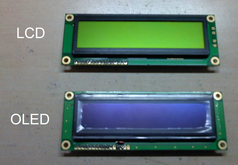
Do I have a LCD or OLED? I purchased the 'Budget Serial LCD Module' but there was no VR1 (not required for OLED) in the kit.
Any thoughts?
Keith
Do I have a LCD or OLED? I purchased the 'Budget Serial LCD Module' but there was no VR1 (not required for OLED) in the kit.
Any thoughts?
Keith