Low power operation?

radiogareth

Senior Member
I've wanted to us some IR remote control for a while and finally got round to it.
Using the standard Rudolf IR TX board I measure the standby current - on 3 cells it's about 0.15uA - not bad for sitting in a loop checking.
Code:
' ***** main loop *****
' Based on Rudolf example with added pullups
'loop until switch is pressed
	pullup on
main:
	if pin1 = 1 then tx_1
	if pin2 = 1 then tx_2
	if pin3 = 1 then tx_3
	if pin4 = 1 then tx_4
	goto main
tx_1:
	let b1 = 1 ' Code 1
	goto tx_ir
tx_2:
	let b1 = 2 ' Code 2
	goto tx_ir
tx_3:
	let b1 = 3 ' Code 3
	goto tx_ir
tx_4:
	let b1 = 4 'Code 4
	goto tx_ir
'transmit code 10 times for increased reliability
tx_ir:
	for b2 = 1 to 10 ' send infrared code 10 times
	infraout 0,b1 ' send code
	pause 45 ' wait 45 milliseconds
	next b2
	goto main
So that project can go ahead just fine - I have updated the code to use 4 buttons and the built-in pullups. No need to see it TX so I deleted the visible LED, mainly as input C5 does not have an internal pullup and can't be used as an output. Yes I could add a resistor and keep both, but how many IR remotes have a visual indication anyway.

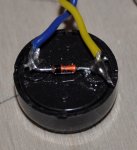
I then looked at my moneybox code - using the piezo trigger. This code uses 1.5 mAmps, so not really suitable for battery power. Why the difference and what is causing it?
Code:
'simple tap on, off software, using a piezo element on an input.
'Wired with a 5 volt zener across it to clip the signal to -0.7 and +5.0
'You can add a whole sequence of button presses each stage doing something
' else like light patterns. The limit
'is your patience in tapping to get back to all off!
lightoff:	
	If pin3 = 1 then waitup	'if the button is pressed on pin 3					'the software jumps to the lighton procedure 	
	goto lightoff		' loops around and does it again......
lighton:	
	If pin3 = 1 then goto waitdown
	goto lighton
	
waitup:
	high 0,1,2	'turns on whatever is connected to the high power output
	pause 1000'waits for 1 second before it does anything else
	'this gives you time to take your finger off the button/taps to stop!
	goto lighton

Waitdown:
	low 0,1,2		'needed here to turn the light OFF having returned from on.
	pause 1000'waits for 1 second before it does anything else
	'this gives you time to take your finger off the button!
	goto lightoff
Thoughts and sugestions very welcome!

Gareth
 
Last edited:

srnet

Senior Member
Circuit diagram would help.

What happens to the current consumption if;

You remove the zener ?

You remove the piezo ?
 

radiogareth

Senior Member
Thought it might be the peripherals: It's the code: I tried my piezo code in the Rudolf IR board and the current consumption was the same (ie the higher figure).

I have yet to draw the ckt. Piezo between ground and input 3, zener across piezo. LEDS on o/p 0,1&2

Still wondering......
 

srnet

Senior Member
I have no idea what the 'Rudolf IR board' is or what processor you are using, but 1.5ma seems about normal to me for a PICAXE....
 

hippy

Ex-Staff (retired)
Staff member
Using the standard Rudolf IR TX board I measure the standby current - on 3 cells it's about 0.15uA - not bad for sitting in a loop checking.
In fact 150nA would be astounding.

Are you sure it was actually drawing such low current as there is no nap or sleep in the code and the 1.5mA for the moneybox project would seem much more typical. Looking at the datasheet around 50uA would seem to be the lowest current with the oscillator enabled.
 

srnet

Senior Member
In fact 150nA would be astounding.
Indeed.

In fact I would offer way over the standard price to get hold of such a PICAXE ...........

Just getting a standard PICAXE down to about 10-20uA takes a bit of care.
 

g6ejd

Senior Member
I think you may have recorded the current drawn on the wrong DVM(?) range as 0.15uA is so small that I don't know many if any standard devices that could measure down that low, even induced currents would be showing up from nearby devices, like a PSU transformer.

Most current (I) ranges will display 2mA, so the lowest reading is likely to be 0.1 mA. A check of the Microchip web shows a typical current consumption in Sleep is 4.3uA and 1.05mA out of that state. Given you have an accurate figure going on to determine typical battery life should be easy though if that's your aim.

At the uChip quoted figures an AA cell woudl last for 76years, an AAA about 33years and an CR2032 about 6years. In all cases the battery shelf life would likely be exceeded before the circuit depleted it!
 
Last edited:

fernando_g

Senior Member
I think you may have recorded the current drawn on the wrong DVM(?) range as 0.15uA is so small that I don't know many if any standard devices that could measure down that low, even induced currents would be showing up from nearby devices, like a PSU transformer.
You would require a Fluke 8808A or similar meter. They are not cheap, though. About US$790
 

srnet

Senior Member
You would require a Fluke 8808A or similar meter. They are not cheap, though. About US$790
Or build a simple circuit that switches a high value resistor in series with the power line, and measure the voltage across the resistor.

As long as the voltage drop is small, it wont affect the circuit operation.

Even some cheap multimeters can read 0-200mV

I use one of these 'current probes' for measuring current consumption on a scope .....
 

g6ejd

Senior Member
The problem is (as stated) with a supply current of 0.15uA the circuit impedance is effectively 33Mohms at 5V, so introducing say 10M in-series is going to be significant as that would introduce a potential difference of ~ 1.5V (0.15uA x 10 Mohms) reducing the supply to the PIC by that amount.

Once an accurate current has been measured, then some more obtainable values for these various techniques can be established.
 
Last edited:

Dippy

Moderator
No, but hey... :)

You'll have to be careful with your shunt arrangement.
With a micro that may require higher-power startup or even occasional function then a shunt may cause a voltage-drop-too-far or if not too far might cause a BOR.
Ideally a smaller shunt with switchable gain or that capacitive method which I can't find a picture of.
 

srnet

Senior Member
You put a switch across the series resistor, when the circuit is stable, in a known loop or in a sleep state, open the switch.

I have not had problems with PICs reseting when the resistor introduces a voltage drop of less than 200mV.
 

BeanieBots

Moderator
You put a switch across the series resistor, when the circuit is stable, in a known loop or in a sleep state, open the switch.

I have not had problems with PICs reseting when the resistor introduces a voltage drop of less than 200mV.
Agreed, but with a 1M3 source impedance on the power supply, it wouldn't take much to cause a complete drop-out.
Some very good decoupling would certainly be in order.

It would also be nice if the OP would come back with comments relating to original figures 'measured'.
 

Dippy

Moderator
Exactly. I was simply pointintg out a possible problem to less experienced people.
Solutions are often easy after a potential pitfall is pointed out.
 

radiogareth

Senior Member
The OP (me) is busy with a lot of other things....but thanks for the various comments....
Firstly, our multimeters are sub £20 units from Rapid Electronics, but I also have "2 for a £5" ones I bough from Maplins a few years ago and they all have a 200uA scale on them. I have been building sub uA cmos logic based circuits for 25+years and have regularly watched the current drop once the chip is in a stable state down through the sub uA level. Battery life and user reports of battery life all back this up, so I believe what my DMM is telling me.

I have just re-measured the IR sender, and tried the chip in another board (different hardware). I maintain that it appears to be using 0.2 uA.

Sounds too good to be true, so maybe it is......

Perhaps someone else would like to try the code in an 08M2 and report their findings? Using the same DMM I measured the other code (at top of original post) and that shows 0.7 mA, about what I'd (and you all) expect.

Technical were unable to advise, suggesting that people on the forum were better placed to advise on low current consumption applications.

So what way(s) can I achieve the following?

'Standby' current less than 0.2 mA, so I have battery life of at least a year using AA cells.
Instant (or apparently instant by human standards) reaction to an input, the trigger MUST be reliable.

My thoughts are along the lines of....reduce clock speed until event seen (how to?)
Store the event on a capacitor and use nap, sleep, doze etc (which work best) to extend the battery life, waking up periodically to look at the capacitor voltage. Costs 1p more plus hardware change (PCB)

What is really needed is 'wake up on port change' as supported by native PICs, if only......but then my pupils can't add simple tunes and write their own software.
 

radiogareth

Senior Member
'Problem' solved, the miserly chip will not now reprogramme, so maybe it was curling its toes up and has now finally expired.

Shame, I thought I was on a winner there :) The code as published by me uses 0.8 mA whilst in the loop an a 'normal chip'.


Question remains though, how to get reliable reaction to an event whilst using minimal power and sticking with PICAXE code?
 

lbenson

Senior Member
This thread: "Low-Power Battery Backup Reference Design" (http://www.picaxeforum.co.uk/showthread.php?8353) showed an 08M constantly monitoring an input line and idling at 31 microamps (according to my cheap dmm).

It has been running on the same 3 AA batteries for over 4 years, blinking an led every 7 seconds. It runs at 31kHz, so continually monitors the input line at slow speed. Newer M2 and X2 chips may achieve more savings by napping briefly.

Regarding catching the input signal, how fast is "instantly"--what is the duration of the pulse?
 

radiogareth

Senior Member
OK, very helpful, that sort of consumption would be fine.
Pulse duration - I really can't remember, but I'd guess it was around 1 mSecond, not sure yet how much my pulse-shaping zener has changed the signal shape - scope at work and I'm at home :-(
I'll read up osccal - AFAIK it has been replaced by setfreq?
That along with disable BOD and ADC module should do the buisness.
Other things pressing now, will revisit later.

Thanks
 

lbenson

Senior Member
A one millisecond pulse would likely be missed. Running at the normal speed, 4mHz, a tight loop checking an input would probably execute on the order of a thousand times a second. At 31kHz, it will be 1 128th that, or about 8 times a second. I would guess that your pulse would need to be on the order of a quarter of a second for it to be reliably caught by polling. So perhaps you would want a do-nothing loop with an edge-triggered interrupt.
 

HertzHog

Member
I too would like to reliably catch a pulse (from the LED of an electricity meter). Not sure how long but say its 1/20th of a second up to once a second. I'm not sure the flash would send a LDR from low to high as ambient light makes choosing the optimal resistance difficult. Ideally I need to catch both edges and detect the flash on the basis of its shape. How would you code that concept?
HertzHog
 

radiogareth

Senior Member
I too would like to reliably catch a pulse (from the LED of an electricity meter). Not sure how long but say its 1/20th of a second up to once a second. I'm not sure the flash would send a LDR from low to high as ambient light makes choosing the optimal resistance difficult. Ideally I need to catch both edges and detect the flash on the basis of its shape. How would you code that concept?
HertzHog
An LDR is a lot slower than ideal, go for a phototransistor or even another LED - this has been recently used in circuitry by Elektor Electronics. A quick google found this: http://www.merl.com/reports/docs/TR2003-35.pdf which explains it well.
I need to measure the pulse duration now before I can progress, hopefully will have time later.
Be interested to hear more about why you need the shape captured?
 

HertzHog

Member
I think it is a sharp flash on then off so capturing both edges after a standard width would seem likely to give best noise immunity.
 
Last edited:

hippy

Ex-Staff (retired)
Staff member
I too would like to reliably catch a pulse (from the LED of an electricity meter).
It would be best to post a new thread for your own project and also look through previous forum posts on the subject.

You need to have reliable detection of the LED flashing but the shape of the pulse should largely be immaterial; it is the rate of pulsing which is usually important and needs to be determined.
 

radiogareth

Senior Member
OK, update, having used the poke to setfreq on an 08M to 31KHz (from the mains monitor listing earlier in the thread) it now will not reprogram, so maybe I am missing something.....
However, all is not lost as I plugged in a 08M2 part which does allow reprogramming. I then realised that I can use 250KHz, 500 KHz and even 1Mhz.
These are my recorded figures:
K31 20uA
K250 205uA
K500 215uA
M1 650uA
M4 780UA
DisableBOD saves just 5uA
I'd need guidance on turning off the ADC module unless on that chip it's normall off until you tell it you want to use the ADC on a pin.
Either way my circuit reacts without any difference on the K250 rate. K31 needs a second tap sometimes to get it to react, but saves serious amounts of battery power. I tried adding a 100nF capacitor across the input pins - needs a good solid tap to charge it up, but then it double detects - ie capacitor too big. I'd guess that with some experimenting I could use the K31 and a small cap to 'store' the input event until the picaxe comes round and has a look at the pin.
#pause to go and find a 1nF capacitor.....which works fine.
So, mission accomplished pretty much, will react to the "penny dropping" and the batteries will last for a long time :)
Code:
disableBOD
setfreq k31
  main:
  	If pinc.3=1 then goto onled
  	goto main
  
  onled:
  	setfreq m4
  	high 0
  	pause 1000
  	low 0
  	high 1
  	pause 1000
  	low 1
  	setfreq k31
  	goto main
I'm suprised more is not made of the benefits of these slower clocks (in the manual), especially as with some simple maths (like the pauses) a lot of stuff could use k31.
 

hippy

Ex-Staff (retired)
Staff member
If pinc.3=1 then goto onled
Pin 3 ( leg 4 ) on 8-pin PICAXE's does not have an internal diode clamp to the +V so if you're using a tapped piezo sensor into that you are in danger of over-volting the input. It would perhaps be better to use a different input or add an external clamping diode. Perhaps also a good idea to post your circuit so we can see exactly what you have.
 

radiogareth

Senior Member
Pin 3 ( leg 4 ) on 8-pin PICAXE's does not have an internal diode clamp to the +V so if you're using a tapped piezo sensor into that you are in danger of over-volting the input. It would perhaps be better to use a different input or add an external clamping diode. Perhaps also a good idea to post your circuit so we can see exactly what you have.
It has a 5 volt zener across it for just that reason. Clamps negative as a normal silicon diode and clamps at 5 volts too, the zener
voltage

Piezo sensor with zener.JPG
No time to draw a circuit, sorry....
 

eclectic

Moderator
Just checking.
Did you mean that a hard reset does not fix it?

I've just run this program with an 08M
on its own in an AXE091 board.

Code:
#picaxe 08M
main:
poke $8F, %00000000
stop

; taken from Stan Swan's posting
; 03 Feb 2005
'%00000000 = 31 kHz ~19bps
'%00010000 = 125 kHz 75bps
'%00100000 = 250 kHz 150bps
'%00110000 = 500 kHz 300bps
'%01000000 = 1 MHz 600bps
'%01010000 = 2 MHz 1200bps
'%01100000 = 4 MHz 2400bps
'%01110000 = 8 MHz 4800bps
A hard reset allows a new download.

e
 
Top