But you see it now? As someone infinitely more experienced than I, do you see and reason why the darlington outputs would be ON, ON, ON, OFF when that state shouldn't be possible?The problem turns out to be that what I was seeing was not what you were seeing, or were expecting me to see.
Problems with motorised macro rail
- Thread starter SteveD
- Start date
Yes I see it now, saved the image to disk, loaded into an image editor and the missing 30% appears.
I agree it looks to be correct, looks like the example given in the PICAXE manual. If any Darlington pin is stuck output high that suggests there's either a fault with the Darlington drive, a short on the board, a mis-wiring, or the signals simply aren't propagating correctly, same reasons and voltage levels may come into it.
Motor drive 1 is controlled by ...
PICAXE Output 2 -> Darlington Input 2, Darlington Input 6
Darlington Output 6 -> Darlington Input 1
Darlington Output 1 -> Motor drive 1
Therefore run the following code ...
Do
High 2 : Pause 500
Low 2 : Pause 1000
Loop
And look at all the pins mentioned. Check the PICAXE Output Pin 2 has a half second pulse, then work through the connections checking all pins are pulsing as would be expected. At some point one should find an input that toggles and an output which doesn't or something like that. That will point to where the problem is.
If using something better than Internet Explorer, you can also right-click images and click 'View Image' to view the image in the browser and you can use scroll-bars or scale the image to the whole browser window.Yes I see it now, saved the image to disk, loaded into an image editor and the missing 30% appears.
Update.If using something better than Internet Explorer, you can also right-click images and click 'View Image' to view the image in the browser and you can use scroll-bars or scale the image to the whole browser window.
She works. ! The steppers both manage to turn properly. Note to all. Do not buy chips from eBay.
Now, there is one part that doesn't work for me. That is the camera won't fire. I did see posts somewhere here about that, and the fix, I didn't read them all as i wanted to tackle the stepper problem first.
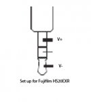
I have a Fujifilm HS20EXR. The cable I am using has 3 wires. Red,Blue, White. When I short red and white together myself, the camera fires. When i short blue and white the camera fires. Red and blue together nothing, hold them together and touch with white, the camera fires. The cable is from a wired remote for this camera. Any ideas on this one.??
Thank you all for your help so far. Very happy bunny right now. Will be more so when I get the camera to fire.
")
While not an absolute, caveat emptor certainly applies and some people won't be surprised at any report that some eBay sold chip don't function as expected.Note to all. Do not buy chips from eBay.
Anyway another example how buying from eBay may simply end up lining the seller's pockets, ultimately costing the buyer more, and cost time and effort from everyone involved in resolving the consequential issues.
Nice to hear you have solved the problem! So it really was the darlington chip?
As for the camera triggering, my circuit uses a optocoupler to short the two contacts. Here is the internal diagram of the coupler:

You have already identified which two wires you need to short together. Just check which one is positive and which is the negative. Connect he positive to the pin 5 and the negative the the pin 4.
It could also be a timing problem. How long do the wires have to be shorted for the camera to take the shot? The current duration is set the 0.4s ('pause 400' line). You may need to increase that.
EDIT:
Another thing could be a too large resistance of the optocoupler resistor. I see now I am using a 470ohm resistor (corrected).
As for the camera triggering, my circuit uses a optocoupler to short the two contacts. Here is the internal diagram of the coupler:
You have already identified which two wires you need to short together. Just check which one is positive and which is the negative. Connect he positive to the pin 5 and the negative the the pin 4.
It could also be a timing problem. How long do the wires have to be shorted for the camera to take the shot? The current duration is set the 0.4s ('pause 400' line). You may need to increase that.
EDIT:
Another thing could be a too large resistance of the optocoupler resistor. I see now I am using a 470ohm resistor (corrected).
Last edited:
1. posts here:Update.
Snip
That is the camera won't fire. I did see posts somewhere here about that, and the fix,
I didn't read them all as i wanted to tackle the stepper problem first.
http://www.picaxeforum.co.uk/showthread.php?20052-Project-hiccup-and-need-help-please/page6&highlight=Nikon
2. If it's similar to the Nikon, one combination to Focus, then add the other wire to fire.
See the two-optocoupler information in the point 1 thread above.
e
Ok, now that you have the rail working, here are a few things that you may want/need to thinker with. First, here is the code with enumerated lines, for easy reference:
http://pastebin.com/VtthHkJP
The 'slack' constant in line 16 should probably be changed.
The 'steppause' should be as small as possible. If it works reliably with 1 then use that.
You have three 'pause' commands in the 'shoot:' subroutine (line 99). The first is the pause (in milliseconds) to wait between the rail finishing one slide and taking the photo. It's purpose is to give the rail and the subject time to stop vibrating, to give the flash additional time to charge and the camera to finish writing the photo to the card. The next pause is 'shutter down' duration. Experiment to see what works best. The last pause is the delay before the next slide. Basically it's the longest exposure you are planing to have.
You want to make the delays as small as possible as the default values are a bit conservative and quite slow (taking >100 photos can take a long time) though they should work for most setups.
Lastly, a few photos of the finished rail would be nice
I am going to try and get this shooting issue sorted, then I will put it all together in a cradle or box and show it to you.
Thanks again guys.
EDIT:
He shoots, He Scores !!.
Success again lads. Turns out that the wire part of my wireless shutter remote (2.5mm jack to mini usb) that connects to my camera works fine. I shorted the pcb camera wires on the 2.5mm jack. Conections A and C
As soon as I touched these parts of the jack, the camera started firing for me. :0)
One very happy bunny.
I threw something together last night in the form of a housing for my board, but will wait till my other IR receivers arrive and get it finished before posting a picture for you to see.
Thank You all very much for the help and pointers.
This project has made a happy man very old. hahaha.
Cheers.
Steve
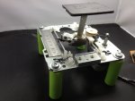
Edit: Hi guys, this is one of my finished rails. I ended up with 2 with all the parts I ended up with.
The board is off to the right just now, but it will be housed inside a small case from a usb vga monitor supply when i get my other Ir receiver in. Everything is connected to the board via 3.5mm phono jacks, including the power, which, instead of the battery pack, I have used an old Nokia phone charger. Works a treat.
With this motor and programmed to 01 with remote i get 80 steps per mm which is way too much for me I think, but one day I may get a microscopic solution on the lens and it will be good then.
Cheers again.
Thanks again guys.
EDIT:
He shoots, He Scores !!.
Success again lads. Turns out that the wire part of my wireless shutter remote (2.5mm jack to mini usb) that connects to my camera works fine. I shorted the pcb camera wires on the 2.5mm jack. Conections A and C
As soon as I touched these parts of the jack, the camera started firing for me. :0)
One very happy bunny.
I threw something together last night in the form of a housing for my board, but will wait till my other IR receivers arrive and get it finished before posting a picture for you to see.
Thank You all very much for the help and pointers.
This project has made a happy man very old. hahaha.
Cheers.
Steve
Edit: Hi guys, this is one of my finished rails. I ended up with 2 with all the parts I ended up with.
The board is off to the right just now, but it will be housed inside a small case from a usb vga monitor supply when i get my other Ir receiver in. Everything is connected to the board via 3.5mm phono jacks, including the power, which, instead of the battery pack, I have used an old Nokia phone charger. Works a treat.
With this motor and programmed to 01 with remote i get 80 steps per mm which is way too much for me I think, but one day I may get a microscopic solution on the lens and it will be good then.
Cheers again.
Last edited:
Looks nice I am a bit sceptical about that large platform on a thin holder, though. Doesn't it vibrate?
I am also thinking about getting something a bit 'stronger'. Possibly a 10X objective that would give me something like 0.01mm DoF which is right at the limit of what my rail can current do.
PS: It's always better to make a new post because if you simply modify the existing post people who have subscribed to the thread do not get notified of a change. I have discovered your edit by accident.
I am a bit sceptical about that large platform on a thin holder, though. Doesn't it vibrate? I am also thinking about getting something a bit 'stronger'. Possibly a 10X objective that would give me something like 0.01mm DoF which is right at the limit of what my rail can current do.
PS: It's always better to make a new post because if you simply modify the existing post people who have subscribed to the thread do not get notified of a change. I have discovered your edit by accident.
Last edited:
The platform doesn't wobble when in small steps, in large steps it does a little, but with large steps I am just getting the rail set up. The platform is on a bit of aluminium and is held in place with epoxy resin, so relatively soild. If needs be, i will coat the metal upright to the platform with epoxy, making it a lot stronger and reduce and vibration. I will play around with it and see where it goes. I have taken a couple of stacks so far, but finding it hard to find anything to photograph outside just now.
Here are some images I have done using the rail.
I found a DEAD MOTH in my shed. This is a stack of 120 images.
A slice of the steel rule I used for the rail.
A silver Sixpence I have from 1930.
I also used the rail as a steadying platform and to aid focus in THIS video. The Globby is around 1.75mm long.
Nice photos (your lens combo certainly seems sharp enough) and I love the globby video! Even though I have thousands of macro photos I still haven't captured a springtail. Will have to try harder, come spring. I understand your frustration by the lack of suitable subjects to photograph. I have also finished my rail during the winter.
BeanieBots
Moderator
Very impressive depth of field too.
Plenty of them around just now. try looking under bits of damp bark in woods, or on park benches. :0)Nice photos (your lens combo certainly seems sharp enough) and I love the globby video! Even though I have thousands of macro photos I still haven't captured a springtail. Will have to try harder, come spring. I understand your frustration by the lack of suitable subjects to photograph. I have also finished my rail during the winter.
Thank You. :0)Just one word to describe the stills and video:
Excellent.
e
Very impressive depth of field too.
Thanks.
It's not all down to the software. I used Zerene Stacker to do the stacking, then spent most of the day touching up the bits that weren't right on the moth. The others were done in Photoshop CS5. :0)I guess that's the focus stacking software - what was used?
Here's one for you...this problem has just started this afternoon.
When setting the focal range, the rail starts, goes till I tell it to stop, sometimes it takes a couple of presses of a key on the remote, the rail starts to move back to the start, but it stops part of the way there. I am trying to capture a bush cricket (dead loss from the delivery for my lizards). I have turned the power off to the rail and left it for several minutes and tried again, and also tried different sized steps, but the same thing. It only goes back about 1cm or so.
Any ideas?
Hmmm... that's really strange. Never happened to me. It has just started doing this (worked before)? Can you do a continuous slide without the rail stopping on it's own (AV/TV prefix)? Does the rail correctly remember the needed number of steps and take that many photos when the Power button is pressed? Does it always stop after the same number of steps or not?
If you do 10 manual jumps forward and then back do you end up at the same position?
Does the same thing happen with the step size 01?
The more info you give better are the chances of finding the cause.
If you do 10 manual jumps forward and then back do you end up at the same position?
Does the same thing happen with the step size 01?
The more info you give better are the chances of finding the cause.
I can do continuous slides in any size step.Hmmm... that's really strange. Never happened to me. It has just started doing this (worked before)? Can you do a continuous slide without the rail stopping on it's own (AV/TV prefix)? Does the rail correctly remember the needed number of steps and take that many photos when the Power button is pressed? Does it always stop after the same number of steps or not?
If you do 10 manual jumps forward and then back do you end up at the same position?
Does the same thing happen with the step size 01?
The more info you give better are the chances of finding the cause.
I do end up in same position when moving 10 back and forth.
I go back to same position when I do any size of step.
Everything works as normal, apart from when the rail does the focus range, when I press a key to go back to start ready to shoot, it only goes part of the way. Weird as I did a couple of stacks earlier and it worked fine.
Sorry, can't think of anything at the moment. I know it's not really convenient but you can always move the rail manually by either stepping or sliding. The photo-taking sequence should still work. That is why I haven't programmed the rail to automatically start shooting, in case you need to make fine adjustments of the start position.I can do continuous slides in any size step.
I do end up in same position when moving 10 back and forth.
I go back to same position when I do any size of step.
Everything works as normal, apart from when the rail does the focus range, when I press a key to go back to start ready to shoot, it only goes part of the way. Weird as I did a couple of stacks earlier and it worked fine.
Not to worry. When it does stop early, the photo sequence still works, but from the point it stopped at, so I can do it manually, or keep turning it off and leaving it. It took me 3 goes last night to get a STACK. It is still better than trying to hand hold the camera whilst doing a stack. At least it doesn't look like i am trying to photograph an earthquake. :0)Sorry, can't think of anything at the moment. I know it's not really convenient but you can always move the rail manually by either stepping or sliding. The photo-taking sequence should still work. That is why I haven't programmed the rail to automatically start shooting, in case you need to make fine adjustments of the start position.
Thanks again Domjan.
Not at all. I really can't think of any reason why it would be acting this strangely. There should be no difference between a continuous backward slide and returning to the start position. You say that the rail correctly remembers the needed number of slices (let's say 10) as evident from the correct shooting sequence, but it reverses only a few 'slices' (let's say 5)? It has to be some kind of a weird hardware glitch. Did you try powering the circuit from the batteries?
Also, I didn't quite understand what you mean by "so I can do it manually, or keep turning it off and leaving it."? What are you doing, exactly? You should use your CH- button to position the rail to a correct starting position and from there shooting should work correctly. If it doesn't (stops early) that would mean that a wrong number of slices got memorised.
Also, I didn't quite understand what you mean by "so I can do it manually, or keep turning it off and leaving it."? What are you doing, exactly? You should use your CH- button to position the rail to a correct starting position and from there shooting should work correctly. If it doesn't (stops early) that would mean that a wrong number of slices got memorised.
By manually I mean the long way, haha. I have a wireless shutter remote, and of course the remote for my rail. 1 in each hand, move one, shoot one etc.Not at all. I really can't think of any reason why it would be acting this strangely. There should be no difference between a continuous backward slide and returning to the start position. You say that the rail correctly remembers the needed number of slices (let's say 10) as evident from the correct shooting sequence, but it reverses only a few 'slices' (let's say 5)? It has to be some kind of a weird hardware glitch. Did you try powering the circuit from the batteries?
Also, I didn't quite understand what you mean by "so I can do it manually, or keep turning it off and leaving it."? What are you doing, exactly? You should use your CH- button to position the rail to a correct starting position and from there shooting should work correctly. If it doesn't (stops early) that would mean that a wrong number of slices got memorised.
I have powered it with the battery pack too, but the same thing happens. I have powered the rail off, left it and it works, but then the next time I try it does the same thing.
I managed to get the same remote as yourself and thought it might be me doing something wrong.
I have also got my spare pcb, with another picaxe and darlington on it, I swapped them over and the same thing.
I tried it this morning and it is working fine.
It is very up and down, works one minute, not the next. It is nothing much for me to worry over really, I can get by.
So this is what I do when it doesn't work.
Summary:
I set the camera on it's tripod, focus is set, and I move the camera on it's own manual macro rail to get it to the start position as best I can. I then do any final adjustment using the rail by programming 01 or 02 etc on the remote and using CH+/- to adjust. I then press Vol- to start the rail off. I then press CH+ normally to tell it to stop, it then either goes back to the start, or stops after a short distance. If it goes all the way, I press power to start the shoot. If it fails on me, I start over or turn it off, then try again after a smoke and freak out break. :0)
To be honest m8, the rail working like this is a lot better than having to hand hold the camera and do it that way, so I am still over the moon with it.
EDIT: I just noticed you mentioned there to use the CH- button to position the rail at the start. Could it be that if I use the CH+ button at all, this could cause my rail to stop early? I am going to try it again now.
Thanks.
Yes, that's it fella.
I just tried it again. I am still getting used to the direction of it all, sometimes i may go too far and use CH+ during the final adjustment for stacking. This seems to cause the error as I did it just now using only CH- and it worked first time.
I used both CH buttons to test, and it failed. Seems that is the problem.
Coolio.
All sorted now.
Thanks again.
I've got no idea what has just happened. Is the rail now working correctly? What button you press to stop the range calibration should make absolutely no difference. The program does not even process the key, just checks to see if there is ANY modulated IR signal.
I am also a bit puzzled as to why you would manually slide the rail and manually take the photos? Even if the 'back to home' slide fails, the Picaxe should still have a correct number of steps (slices) memorised. You would simply reposition the rail (by using the CH- and CH+ buttons) and press the Power button to start the automatic shooting sequence. You don't turn the rail off (because it will forget the needed number of steps) and if you change the step size you return it to what it was during the (Vol-) calibration. Did you find the optimal step size for your DoF? I hope you are not using the 01 or 02 during the shoot as it's probably a definite overkill.
As for disconnecting the battery and waiting... the Picaxe remembers only the step size, not the number of steps. Step size it remembers in it's eeprom so once you have found the optimal step size, it will be saved even if the power is completely disconnected.
Is the rail now working correctly? What button you press to stop the range calibration should make absolutely no difference. The program does not even process the key, just checks to see if there is ANY modulated IR signal. I am also a bit puzzled as to why you would manually slide the rail and manually take the photos? Even if the 'back to home' slide fails, the Picaxe should still have a correct number of steps (slices) memorised. You would simply reposition the rail (by using the CH- and CH+ buttons) and press the Power button to start the automatic shooting sequence. You don't turn the rail off (because it will forget the needed number of steps) and if you change the step size you return it to what it was during the (Vol-) calibration. Did you find the optimal step size for your DoF? I hope you are not using the 01 or 02 during the shoot as it's probably a definite overkill.
As for disconnecting the battery and waiting... the Picaxe remembers only the step size, not the number of steps. Step size it remembers in it's eeprom so once you have found the optimal step size, it will be saved even if the power is completely disconnected.
Hi Domjan. Sorry I have not been back on since my last post. I gave up as I took bad with my Multiple Sclerosis. I have now, however, got back on it and all is good. The rail works perfectly and I actually got round to making a case for the PCB. Apple are at least good for one thing. I used an iPod case. I also changed the platform on the rail to a cheap tripod quick release after your concerns of wobble, which it did start doing.I've got no idea what has just happened.
I am also a bit puzzled as to why you would manually slide the rail and manually take the photos? Even if the 'back to home' slide fails, the Picaxe should still have a correct number of steps (slices) memorised. You would simply reposition the rail (by using the CH- and CH+ buttons) and press the Power button to start the automatic shooting sequence. You don't turn the rail off (because it will forget the needed number of steps) and if you change the step size you return it to what it was during the (Vol-) calibration. Did you find the optimal step size for your DoF? I hope you are not using the 01 or 02 during the shoot as it's probably a definite overkill.
As for disconnecting the battery and waiting... the Picaxe remembers only the step size, not the number of steps. Step size it remembers in it's eeprom so once you have found the optimal step size, it will be saved even if the power is completely disconnected.
Thanks again for sharing your design, and thanks to all of you for your help on this.
Steve.
Thanks again.
I have a friend who is attempting to make this rail now, but he is struggling so I put together a layered photoshop file to guide him through the board set up.
If you or anyone wants it, feel free to download it from this address.
www.stevedargie.pwp.blueyonder.co.uk/Downloads/circuit.psd
You just need to look through it and make each layer visible when you need it.
Cheers.
Hi Domjan. Thanks.Hi Steve! I must say that your rig looks much better than mine and I am glad it's now working OK. Sorry to hear about your condition.
I have a friend who is attempting to make this rail now, but he is struggling so I put together a layered photoshop file to guide him through the board set up.
If you or anyone wants it, feel free to download it from this address.
www.stevedargie.pwp.blueyonder.co.uk/Downloads/circuit.psd
You just need to look through it and make each layer visible when you need it.
Cheers.
nerdegutta
Senior Member
This circuit.psd is an amazing walkthru.
Thanks.This circuit.psd is an amazing walkthru.
Thanks m8. Of course you can use it. I uploaded it to give something back for the advice I was given and getting the idea from you in the first place.That looks great! Much nicer than my scribble
Hello, everyone.
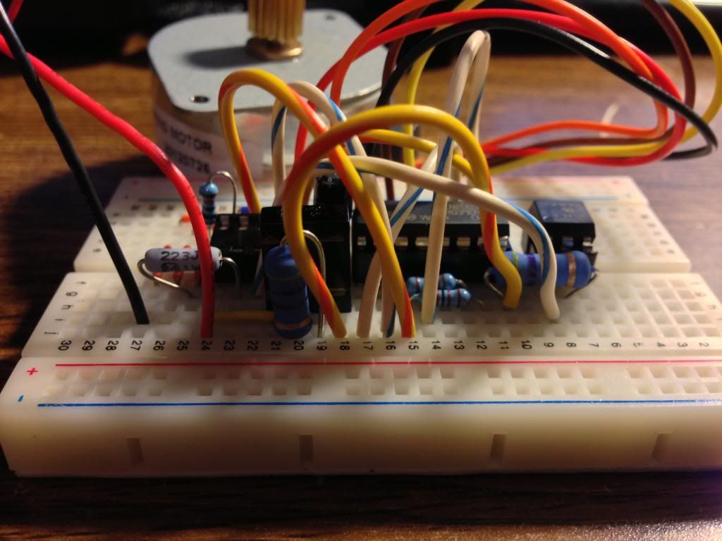
I'd first like to thank the original author and the poster who developed the .psd schematic; you've done amazing work and I've enjoyed assembling your design.
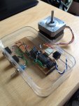
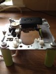
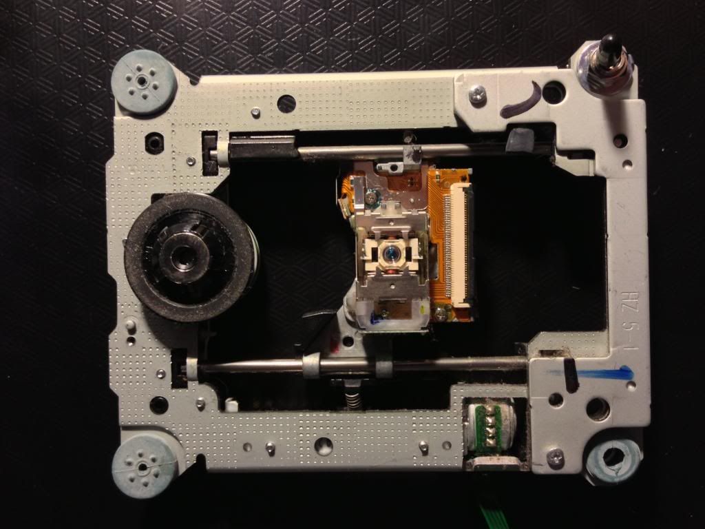
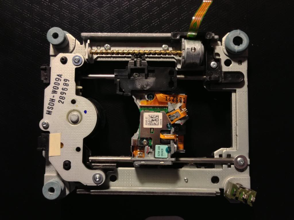
I do have one question, in regards to the mechanics of the stepper motor and rail. I've assembled the circuitry and programmed the picaxe IC, yet I've been unable to figure how the unipolar stepper motor connects to the rail. Is the rail featured in the my photos not compatible with this project?
(Picaxe IC was still in the mail when I took the breadboard shot)
I'd first like to thank the original author and the poster who developed the .psd schematic; you've done amazing work and I've enjoyed assembling your design.
I do have one question, in regards to the mechanics of the stepper motor and rail. I've assembled the circuitry and programmed the picaxe IC, yet I've been unable to figure how the unipolar stepper motor connects to the rail. Is the rail featured in the my photos not compatible with this project?
(Picaxe IC was still in the mail when I took the breadboard shot)
I am afraid that could be the case. Your rail seems to be directly driven by a small bipolar stepper motor. Mine was driven by a small solar motor so I had a very nice built-in set of reduction gears. You could possibly fit a long screw (threaded rod) to your stepper motor, mount it parallel to the rail, mount a nut on the rail's central part and disengage the original worm drive.Is the rail featured in the my photos not compatible with this project?
Thank you for your quick response, dsvilko!
Excellent idea; I'll give that a try this weekend! In the event I'm not clever enough to rig this current rail up, would you happen to recall out of what brand and model of DVD-ROM you pulled your rail? Or have suggestions for similar drives?You could possibly fit a long screw (threaded rod) to your stepper motor, mount it parallel to the rail, mount a nut on the rail's central part and disengage the original worm drive.
Last edited:
The drive I used was an old Sony DVD player. I did try a no name cheap model first as my Sony still worked, but I have a PS3 to play DVD's so hey ho! The cheap model had the same rail as you have there, the Sony had the one I ended up going with. Cog wheel driven rather than the worm screw.Thank you for your quick response, dsvilko!
Excellent idea; I'll give that a try this weekend! In the event I'm not clever enough to rig this current rail up, would you happen to recall out of what brand and model of DVD-ROM you pulled your rail? Or have suggestions for similar drives?
And thanks for commenting on my .Psd drawing.
I have a problem with my build of this project, can anyone help me please? I am a reasonable novice but I can understand the concept of the darlington and optocoupler etc. Plus I do coding for a living, though obviously not this form of Basic.
Firstly, the PSD is excellent, however I had to ungroup the 'joining wires' layer to make each sub layer visible, otherwise the grouped layer was invisible in CS5.1. This may need to be re-done or noted somewhere. Also no motor connections on the PSD. Though the 4 outs on the Darlington are fairly straightforward finding the right 'common' line was not so easy for me. Stepper motors are new to me.
OK, I'm using the 08M2. Status of problem. I can't get any response, not even a shudder from the motor. Power is definitely getting to it as it's holding solid (can't physically turn it, and I can feel vibratory resistance). Testing each wire on the motor out of circuit produces expected shudder, and the motor is brand new. One thing with the motor is that I'm presuming Phase A is step 1, Phase /A is step 2, Phase B is 3, /B is 4. Motor datasheet on below link to my website, where circuit pics, .bas file etc are.
I've cleared the channels between strips with a fine screwdriver, measured the resistance of all connections and components. On power up, even without sending any IR via the remote I have the situation where the stepper is in 'hold' mode.
I've used two different power supplies, 3x NiMh and a 4.5v powerpack cut down to 4.1v with a commercial fan speed controller. I've measured the outputs and inputs of chips and the line to the stepper. All parts were bought from an electronic store, not e-bay. I've upped the capacitor to a 100uF 10v electrolytic as motor current is 1.1A per phase, this capacitor is correctly mounted for a polarised capacitor. I also programmed the Picaxe 08M2 on the beginner kit board rather than the project board, to minimise component interference. The program is exactly as original (cut and paste) and works in simulation. Programming the chip went without a hitch, no errors. All the chips were put in after all soldering, so no heat issues.
I measured voltages across the board without the motor connected, see my website link below for Excel file Voltages Measured.
Hi Res pictures of the board top and underneath, bas file, measured voltages and motor datasheet are http://members.iinet.net.au/~rextal/Picaxe cd macro rail/
Help would be greatly greatly greatly appreciated as I now have a MPE65 which not having an autofocus system, and hence motor, cannot be controlled via Helicon Remote, which is my usual tool of choice for remote control to take focus bracketed shots.
bfgstew
Senior Member
You say 4.5v to 4.1v to run your motor? Sounds a tad on the low side, mine runs off 12v and that powers the chip set via voltage regulator to get a stable 5v for the chip.
Have you tried swapping the motor wires around? Mark them 1,2,3 and 4, then swap 1 and 4, if no good swap 2 and 3, if no good finally swap 3 and 4.
I have had a brief look at your photo's but nothing jumps out just yet, but will have another look.
It does say on the motor data sheet drive voltage = 12v................maybe your answer??????
With this circuit, the stepper will always be in a 'hold' mode when the power is connected so that's normal. From your post I didn't quite understand how much of your circuit is working correctly. Did the picaxe accept the programming and is it working? Have you examined the picaxe and the darlington outputs with a LED probe (just a LED and a resistor in series connected between the test point and the ground (for picaxe) and test point and the VCC(+) for the darlington. If the LED is blinking happily then the problem really is with the stepper. I also have a 12V stepper but it's quite happy with a 4.8V power supply (with reduced torque but still enough to move the rail). If you have wired the stepper incorrectly you should still see (or feel) a shudder.
EDIT: Ok, I have re-read your post and am I correct in understanding that you have indeed tested the darlington outputs and that they are 'firing' correctly? In that case, maybe your stepper is simply too slow. Try uncommenting the 'Pause 1' line in the onestep loop (or even increase the pause).
EDIT: Ok, I have re-read your post and am I correct in understanding that you have indeed tested the darlington outputs and that they are 'firing' correctly? In that case, maybe your stepper is simply too slow. Try uncommenting the 'Pause 1' line in the onestep loop (or even increase the pause).
Last edited:
Firstly, thank you for your prompt replies. Greatly appreciated.
I did try to say in my post that the picaxe did accept the program without errors. In fact I programmed it several times, with minor code variants to try and test out different code aspects. The latest program is the exact cut and paste. As mentioned I did the programming on the separate PICAXE supplied kit module without any other circuits to interfere.
And yes, I'm definitely aware it's a 12V stepper but there's a reason. I first read about this project on http://www.diyphotography.net/create-an-automated-macro-rails-for-image-stacking, not on the picaxe forum, and there a 12V motor from a floppy drive was used. I've looked at several 3 1/2 floppies but all the ones I could get hold of were I think 5V and were BiPolar so no good. I'd guess only 5 1/4 or very early 3 1/2's use a 12V motor. I think in the discussion it was asked if a 5V motor would be better and the response went on the lines of it would but 12V was fine as the current demand would increase and provide more torque (sorry, but I couldn't find that part on the conversation again when I checked). I have however ordered a 5V stepper (from ebay) but sadly the local electronic stores here only stock 12V ones which is frustrating. A quote from that site " Unipolar stepper (12V 1.8deg) connected to ULN2003A:".
Aside from that to me I would logically say that if the voltage isn't high enough to drive the motor it also shouldn't be enough to allow it to hold. I can tell you I did put a bit of effort into turning it whilst in holding mode and gave up as I was afraid of putting too much pressure on it and damaging it. To me this suggests there's quite a bit of power going through and that if it can hold position that well it should be able to step. It doesn't have any gearbox built in so there's no reverse mechanical advantage working against me turning it. Mind you, I admit I know very little about stepper motors so perhaps it only requires a little to hold but more to step. My experience with standard DC motors is that running a 12V motor at 6V really isn't a problem, with speed and torque being roughly linear. I did do some homework and read up about steppers as they've always intrigued me and understand the basic principles but there's always more involved than basic principles.
And I had considered an input of 12V and cutting down as you say but I'll admit I'm a novice. I look at the picaxe suggested circuits and follow them but if I have to put two together into a joint circuit I get a bit lost. As such I didn't want to alter the circuit till I got at least one working. A few friends would be keen to have one too. If you can provide the modification to do this from a 12V or 9V supply I'd be happy to implement it. I have over the years collected several power packs of various voltages, most are 9V so that'd be my preference unless you think that also won't be enough for a 12V stepper.
And it is good to know the motor should be in holding mode prior to any IR commands being issued.
I will play with the order of the wires and see where I get from there. I've used an electricians terminal bridge so it's easy to test each combination out. I was hoping the phase A /A B /B meant something as I've not had any success researching that on the web.
Thanks to all.
I don't have much experience with steppers but as I have said, mine is also 12V and it's got more than enough torque at 5V. I can turn it by hand but not easily (I don't think you can easily break a stepper that way). I simply don't find it likely for that to be the problem. I did hear that some steppers are too inert to reliably turn at high speeds, hence my suggestion to add a short pause between the steps (have you tried it?). What is the standard speed (frequency) of the 08M2, anyway? If it's faster than my 08M mark 1 that that could definitely be a problem.
Have you actually checked that all the 4 stepper wires are getting the signals from the picaxe/darlington? Can you check that there is no problem with the receiver part of the circuit? Basically, what have you done (debugging-wise) to isolate the problem?
Also, what's the current going through the stepper at 5V? Maybe you are overloading the darlington?