Problems with motorised macro rail

rextal

New Member
Finally got the stepper working.

1) Altered the code to just run an infinite loop without any IR or such to complicate things or require pressing buttons. Added longer pauses, if for nothing else than to provide me time to take multimeter readings.
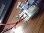
2) Still didn't work but confirmed the darlington was firing 4V on outputs in sequence but amperage was between 200mA and 270mA. I assumed the 1A rating of the stepper is a max consumption but I now think the rating is an operational demand.
3) Hooked up the battery pack of 3x 1800mAh NiMH and noticed motor now jiggling and with a few combinations motor is now stepping properly.

So the assumption about current demand of the stepper being a max demand seems wrong, and this would only be made worse running at 5V instead of 12V which would mean current draw is 12/5 x 1 or over 2A. Even if I hooked up a 12V supply the darlington, as dsvilko alluded to, is overloading it's rating of 0.5A. To persevere with this motor, even with a 12V supply, would require paralelling the darlington or 1 of the high current ones to handle the current or maybe mosfets etc. Which of course means re-doing the circuit as well as supplying cut down to the Picaxe etc. Too much work and thought for the moment.

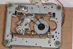
So bottom line is I'll wait for my 5V stepper to arrive. Given the size of the thing in a picture I'd say it's current demand is much lower (going on size as a measure of power, which is mostly true for standard motors). However this motor, seemingly for the robotics market would I think work in a project moving the camera using a flatbed scanner as the carriage (like I saw elsewhere).

Many thanks for your thoughts. Just being able to cut things down to bare minimum to test parts in isolation is always good.
 

dsvilko

Senior Member
I didn't quite understand your calculations. If the stepper resistance per winding is 20ohm (according to the datasheet) then it should draw 5V/20ohm=250mA with the 5V supply, which should be well within the darlington's 0.5A/output.
Did you check that the stepper resistance really is 20ohm? Also, I didn't suggest you run the stepper from 12V as I think 5V should be enough.
 

rextal

New Member
Sorry dsvilko I'm not electronics expert, but am learning with this project. I'm more than happy to be corrected:), in fact I don't like it when people don't and I'm trying to understand something. I was assuming (there's me assuming again:p) the 1.1A phase rating from the datasheet at 12V was for a single coil activation, I wasn't using the resistance to calculate the current demand. After that I was using (power = voltage * current) and was saying in going from 12V to 5V is a current multiplier of 2.4, which was wrong.

And I know you didn't suggest running it at 12V, I'm just postulating as I do have some 2A 12V power packs I could use as a permanent power source.

Also I was unable to put the project aside and prevent myself playing further with it till the 5V motors arrive. I noticed over the span of a few minutes the movement was rather more jarring than I'd expected. I hadn't noticed this earlier as I was just happy it was moving. It's not at all smooth like steppers I'd seen employed elsewhere, and once or twice it'd stumble or take what I thought was a smaller half step or bigger step. The steps also looked too big to be the 7.5 degrees spec (48 steps). After counting I noted it makes 24 steps per revolution, which is 15 degree steps, double the rating. Any clues on that one??? After reading more on driving stepper motors I found several mentions of issues when the delay is too long. Quote from Page 9 http://www.freescale.com/files/microcontrollers/doc/app_note/AN2974.pdf quote "A delay that is too long could create a motor response with noticeably rigid movements and choppy noises with each step" This description seems to fit part of what mine is doing pretty well so I'm going to reduce the pauses down and try that. But I've found nothing about not doing the recommended number of steps.

So I also put some LED's on the darlington outputs (with appropriate resistors) so the firing is visibly illuminated and I could visibly see the firing order. It fires in the following sequence for the darlington output pins 16-13. 16 & 13 then 15 & 14 then 16 & 13 then 15 & 14 and so forth. I'd just like to confirm this is the correct pattern as some of the videos on YouTube with Arduino's don't seem to have that pattern and aside from using an Arduino I'd have thought with both using a Bi-Polar stepper the fire sequence should be identical.

Below is the cannibalised code of yours. It just has main, slide and onestep subs.


symbol slack = 5 ' how many micro steps to add when changing direction
symbol steppause = 2 ' larger number will make it go slower
' - useful if you have a stepper with very few steps per revolution

symbol stepc = b0
symbol s = b1
symbol i = b2
symbol direction = b3
symbol nsteps = b4
symbol nframes = b5
symbol nslide = b6
symbol j = b7
symbol irflag = b8
symbol olddir = b9
symbol contflag = b10


high 1
high 2
low 4

' (nsteps)
eeprom 0, (20)

read 0, nsteps

contflag=0

main:

direction=2
gosub slide
pause 1500
goto main


slide:
if direction<>olddir then ' remove sprocket slack
for i=1 to slack
gosub onestep
next i
endif

onestep:

stepc=stepc+direction-1
let stepc=stepc // 4
lookup stepc, (%00000110, %00000100, %00000000, %00000010), s
let pins = s
if pin3=0 then
irflag=1
endif
return

Regards, Rex.
 

rextal

New Member
are you using the motor on the dvd drive, if so that is bipolar not unipolar motor. i have already built a macro rail based upon an almost identicle tray to one in your pics. have a look on page 17 of manual 2

here a little thread about the rail i built, it maybe of some use
http://www.picaxeforum.co.uk/showthread.php?23525-My-Take-on-macro-rail
Oops, my bad. I stand corrected (again). I meant Unipolar not Bipolar. Every CD drive I've pulled apart (5 now has a BiPolar motor) and all the 3 1/2 floppy drives (4) also the same. I was going to play with using the standard Bi-Polar motor after this project. The Bi-Polar driving circuit looks more complicated so to learn about Picaxe and Steppers I thought the simpler circuit means less to learn. I'm not sure how small a distance increment those motors with the integral worm gear are capable of but it looks like micrometres from CD/DVD specs which should be good. I do however have one with cogs instead of the worm gear to which I can add another step down cog if required.

A question to DSVilko.

I'm curious why you didn't use the Picaxe manual sample code to drive the motor?

steps:
toggle 1 ' Toggle pin 1
pause 200 ' Wait 200 ms
toggle 2 ' Toggle pin 2
pause 200 ' Wait 200ms
goto steps ‘ Loop
 

rextal

New Member
I resolved my step issue. After much searching I found a micro bead of solder splatter well away from any solder point that was crossing tracks causing an incorrect coil activation cycle. I only found this after removing all chips and checking each pin for the IC sockets. Once I cleared the solder the stepper now fires 48 steps as it's supposed to. So finally everything is working as it should. I would highly recommend adding the LED's so you can observe the output from the Darlington.

I ran 250 steps and measured the total distance travelled and calculated I get about .020mm per step now.
picaxe cd macro rail6.JPGpicaxe cd macro rail7.JPG
 

oracacle

Senior Member
i was at one point using half steps.

also i am using a bi-polar motor not unipolar, ie the one that come in rw drives which mean i am using something extremely similar to that of the manual, ppage 18 manual 3

Code:
main:
	for b3 = 0 to 99 					&#8216; start a for...next loop
	gosub lstep 					&#8216; call left step sub-procedure
	next b3 						&#8216; next loop
	for b3 = 0 to 99 					&#8216; start a for...next loop
	gosub rstep 					&#8216; call left step sub-procedure
	next b3 						&#8216; next loop

lstep:
	let b1 = b1 + 1 					&#8216; add 1 to variable b1
	goto step2 						&#8216; goto the lookup table

rstep:
	let b1 = b1 - 1 					&#8216; subtract 1 from variable b1

step2: let b1 = b1 & %00000011 			&#8216; mask lower two bits of b1
	lookup b1,(%1010,%1001,%0101,%0110),b2 	&#8216; lookup code into b2
	let pins = b2 					&#8216; output b2 onto control lines
	return
 

rextal

New Member
First off. To Dsvilko. I now understand why you didn't use the toggles and instead did the lookup, it puts all pin the values in at once. It's quite neat and more efficient use of code space.

And now to other things.

I'm not sure if I'm alone in this but I found the 'Press the AV/TV button to make the next press of Ch Up/Down' a slide a bit cumbersome to use so I altered the code to make volume up/down as directional slide buttons and leave the channel UP/DOWN as individual step buttons only. I then made the TV/AV button the set start point (previously Volume down).

I just my personal preference to control using a single button (I included code below)

Sadly the remote I'm still using is a Panasonic one (it's free) and it only allocates 6 buttons for Universal TV control (vol +/- Channel +/- TV/AC and Power). After I get a Universal remote with the use of more buttons I will also add more features. Two buttons for a 10X step forward and back and another for 'Shoot' so you can take a test shot or just go fully manual if you want. I coded these but remarked them out, if you use it you will need to replace the 'XX' in the case statement to the button you want it mapped to. Speaking of which I know I saw the Sony Remote button code layout somewhere on the Picaxe sites but can't find it again and didn't bookmark it but you can look for the button numbers here http://www.hifi-remote.com/sony/Sony_tv.htm

I'm also looking into adding a 3 digit display so it will show you the number of shots to be taken and then count down as it progresses. Just so I have an idea of how many are left to go.

And lastly I tested an alternate IR receiver (slightly different pin out) BRM-15S8-11 which has near identical specs to the Vishay TSOP1138 and it works perfectly. These are readily available in Perth Australia's electronic shops and don't cost much.


Code:
' Macro focus rail driver
' Unipolar stepper (12V 1.8deg) connected to ULN2003A:
'    green, white, red, brown -> Out1-Out4
'    08m 2 -> ULN In2
'    08m 1 -> ULN In3
' Out4 -> optocoupler for shutter triggering (tip+, sleave-)
' IR detector codes:
'    CH+      back focus
'    CH-      front focus
'    NN       steps in one slide (in 0.01mm)
'    Vol +    continuous slide to back (any key to interrupt)
'    Vol -    continuous slide to front (any key to interrupt) 
'    AV/TV     mark focus (front) and start moving focus back; mark focus
'             end by any key slide to the front of the stack
'    Power    start shooting

symbol slack = 1         ' how many micro steps to add when changing direction 
symbol steppause = 50    ' larger number will make it go slower 
'                          useful if you have a stepper with very few steps
'                          per revolution

symbol stepc     = b0
symbol s 	= b1
symbol i 	= b2
symbol direction = b3
symbol nsteps    = b4
symbol nframes   = b5
symbol nslide    = b6
symbol j	 = b7
symbol irflag    = b8
symbol olddir    = b9
symbol contflag  = b10


high 1	
high 2	
low 4

'           (nsteps)
eeprom 0, (1)

read 0, nsteps

contflag=0

main:


	infrain2  
	if infra<10 then
		infra=infra+1
		infra=infra//10
		nsteps=infra*10
		pause 500  'half second pause between buttons
		infrain2
		infra=infra+1
		infra=infra//10
		nsteps=nsteps+infra
		write 0, nsteps
	endif


	select infra
	case 17 'one forward step:  Channel down
		contflag = 0
		direction=2
		gosub slide
		
	case 16 'one backward step: Channel up
		contflag = 0
		direction=0
		gosub slide
		
	case 19 'continuous forward slide:  Volume down 	
		contflag = 1
		direction = 2
		gosub slide
		
	case 18 'continuous back slide:  Volume up
		contflag = 1
		direction = 0
		gosub slide
		

'	case XX 'times 10 forward step.   Yet to be defined key
'		contflag = 0	
'		direction = 2
'		nsteps = nsteps * 10
'		gosub slide

'	case XX 'times 10 backwards step.   Yet to be defined key
'		contflag = 0	
'		direction = 0
'		nsteps = nsteps * 10
'		gosub slide

'	case XX 'test shot. 			yet to be defined key
'		gosub shoot
 
 
	case 37  'AV/TV - mark focus start and slide till any button:   
		contflag = 0
		nslide=0
		irflag=0
	'	pause 200
		do   
			pause 200
			direction=0
			gosub slide
			nslide=nslide+1
			'pause 200
		loop while irflag=0   'continue till button press
		pause 200'0
		for j=1 to nslide		'return to start based on steps
			direction=2
			gosub slide
		next j
		gosub slide			'remove slack		'
		gosub slide
		direction=0
		gosub slide
		gosub slide
	
		
	case 21 ' Power - start shooting run
		gosub shoot
		for j=1 to nslide
			direction=0
			gosub slide
			gosub shoot
		next j
	endselect
	pause 500
	goto main

shoot:
	pause 300 '5000    
	high 4	' shoot
	pause 400
	low 4
	pause 300'3000    ' wait before the next slide (exposure time)
	return

	
slide:
	if direction<>olddir then	' remove sprocket slack
		for i=1 to slack
			gosub onestep
		next i 
	endif
	irflag=0
	'there is no return here so it continues, doh!!!
lup:
	for i=1 to nsteps
		gosub onestep
		pause steppause
	next i
	if irflag=0 AND contflag=1 then goto lup
	contflag=0
	olddir=direction
	return

onestep:
'	s=direction*2
	stepc = stepc + direction - 1  
	let stepc = stepc // 4		'get the remainder when divided by 4
	'puts the nth value in brackets into stepc according to the value of S
	'the first time s = 0 so it puts %00000110 in stepc
	'%00000110 pin 1 high, pin 2 high		--very first state
	'%00000100 pin 1 low, pin 2 high		--start point
	'%00000000 pin 1 low, pin 2 low
	'%00000010 pin 1 high, pin 2 low
	lookup stepc, (%00000110, %00000100, %00000000, %00000010), s   'original
	'lookup stepc, (%00000010, %00000110, %00000100, %00000000), s  'test
	'pins = 0
	let pins = s
	if pin3 = 0 then   
		irflag=1
	endif

	return
 

dsvilko

Senior Member
I am glad you got it working! As for the slightly inconvenient controls, you don't know how good you have it with the xxM2 parts! :) In the olden days of 08M we really didn't have any memory to spare. I think my poor little 08M had only 2 bytes(!) left over and it really was a struggle for every byte of program space. Today, with the 08M2 you sure can add a lot more software goodies :)
 

oracacle

Senior Member
ou of interst what is the back lash like on the gears,

i have been playing around with a test bed i knocked together from stuff i had to try and thrash out some hardware and software ideas. any how i am currently using some 10x1.5 threaded bar with a 200 step bi-polar motor connected to a thb6064 micro step controller. I have found the backlash on the normal threaded bar to take several clock cycles to overcome.

also found that 64 sub step to a single step is pretty extreme, with that setting i get 12800 step per rotation, i have ordered my lead screw which will have a pitch of 4mm - this will give 0.003125mm per clock cycle/step. i will see if i can find a 3gpp converter and upload some videos
 

rextal

New Member
With the three reduction gears, reducing pulley from motor to gears and the 7.5 degree stepper I'm getting about 0.024mm per step. With the plastic toothed rack I found I was getting way too much slack and sideways movement so I removed that an used threaded metal rod, which luckily for me is a really snug fit to the cogs I am using. Now there is practically no play in the system. I am using it with the 5x Canon MPE-65 lens and using live view via the PC to set start and end points so erratic movement is very obvious.

I've always set the first shot one closer than I want and the last one beyond what I want, I can always ditch them later anyway. I do this as a safety precaution. And because of this I removed the backlash step.

Since then I've made some more modifications which to me made using it easier to use.

I dispensed with the 'slide' in favour of a 10 step forward or backward (that's 10 multiplied by whatever step size you've chosen). I find this much easier to work with.
I put a switch on the board with an LED to indicate it's turned on (didn't do this on my initial board with had LED's to show the darlington output activation to the stepper wires).
I added a 16x2 display (axe 133) retaining the 08M2 on the main board. It now displays simple instructions, confirms step size, number of shots expected, number taken, number remaining, 1 step forward or backward, 10 steps forward or backward, start point set, shooting mode).
 

ema2t

New Member
Hello , here i am reviving this thread.
I m trying to reproduce this great stack rail .
I have not read every pages of this thread and I sorry if I ask questions yet answered.

I am using a 12v 6 wires stepped motor grabbed from a printer. It is connected to the rail with gears .
The ir reciever as been picked from an old Philips dvd player. I think this will cause some issues with the code.
I didn t got a 0.1uf cap and I put a 10uf cap. I dont know if it matters since it s wide larger.

The picaxe 08m2 has been succesfully programmed. Tomorrow I will try my board with leds.
Waiting for your comments, have a nice day !
 

dsvilko

Senior Member
Hi!
While the slightly larger capacitor is not a problem, the stepper motor is. You've got a bipolar motor, as oposed to the unipolar (5 wire) one this board expects. It's slightly harder to drive a bipolar stepper and as a result you would nead a larger picaxe and a different driver circuit.
 

ema2t

New Member
stepped motor

Hi!
While the slightly larger capacitor is not a problem, the stepper motor is. You've got a bipolar motor, as oposed to the unipolar (5 wire) one this board expects. It's slightly harder to drive a bipolar stepper and as a result you would nead a larger picaxe and a different driver circuit.
Hello dsvilko. Thank you for your help. My motor is NMB PM55L-048-TCX3. I couldn't find a correct datasheet, but as you suggest in your tutorial, I joined the 2 (+) wires and I idenfied the "1234" sequence. Seems to me it is unipolar....but I'm a beginner so I can have misunderstood. If I can't make it work properly I'll buy the motor you used.
Here are pictures of the beast
20150304_080824.jpg20150304_080842.jpg

If I got time today, I'll test my board with leds.

Have a good day
 
Last edited:

dsvilko

Senior Member
I think you are right. 6-wire motor should be able to function in both unipolar and bipolar mode. Ignore my last post :) If you have identified the common wires and the correct sequence, it should work.
 

ema2t

New Member
testing board

So I have connected leds to the darlington output. On power on, at first out 1 and 4 are "on" while 2 and 3 are off. Then half a second later 1&4 are off and 2&3 are on. Then no change . I read somewhere I should change the pause duration in the code.
I suppose my tsop isn't good because nothing happens when pressing buttons.
Well as I said it is from a dvd player ( not sony) but I thought the matching dvd player remote control would work...
 

dsvilko

Senior Member
Try searching for "picaxe vsm macro" on youtube. There is a very good simulation how my circuit should work. Maybe that will help with debugging. Don't know about the IR sensor (could be compatible or not) but you definitely nead to send Sony ir codes as they are the only ones picaxe understands. The sensor could work if it's the right frequency even if it's not from Sony tv but you still nead a Sony (or any universal) remote.
 

hippy

Technical Support
Staff member
As dsvilko says the sensor should likely work but the intelligence in recognising key presses is in the PICAXE firmware which expects Sony codes, not in the sensor itself. So the DVD player remote won't work because the PICAXE is expecting Sony TV codes.
 

ema2t

New Member
Yep understood, I've found a SONY remote. ( I didn't know which component was decoding signals ). I'll study the "picaxe vsm macro" video tomorrow morning. I read in the thread that pins were expected to work by pairs . I've got to check this again but the fact 2 leds are on when the 2 others are off seems to be a good news....
My optocoupler isn't a 4N25, but datasheets are similar and as far as I understand it, it won't affect the motor.
Good night !
 

ema2t

New Member
Hello !
My ir reciever is working. Leds reacts when I press Sony remote buttons. I think I've to check the wire order of my motor because he jerks once on power on and that's all.

Stay tuned !
 

ema2t

New Member
Ok , I have changed my motor with a 5 wires motor and identified the "1234" sequence and connected it in the "1324" way.
when I press the ch+ button it moves forward but when I press ch- it goes foreward too... what I am sure is that I had a problem with my 6 wires motor.

the "1324" thing means you cross wire 2 and 3, ok it's done but what if the 1 wasn't realy 1 ? Do I have to try all the other possibility ? ( I don't know if I'm understood )
I tryed 1234 and I obtained the same result. Is it supposed to move if I mess with the wires ?
 

ema2t

New Member
Hey there ! I am proud to say that it's working !
The ULN2003A was faulty...tryed 3 and the 3rd was the right one ! I even tryed a ULN2003AN which worked too.

I prepare my nikon to board connection and prey for a great shooting session tomorrow.
Thank you for advices !
 

skyquake

New Member
Hello!
First of all I want to say thanks to dsvilko for sharing this project with us - it's great...
At the moment I'm waiting for some parts to arrive and then I will start to build my rails and there is one question:
considering that original macro rail was made with Picaxe 08m, but I've got the 08m2, do I have to make some changes to the original code or circuit?
 

dsvilko

Senior Member
I don't think you need to change anything. You'll also get a lot more program space if you need to extend your project with additional features (I think I had something like 1 byte left).
Good luck!
 

ManuelR

New Member
Hello, unfortunately the link for downloading the circuit diagram (circuit.psd) is no longer active. Can anyone please share it again? Greetings from Mexico.
 

SteveD

Member
Hello, unfortunately the link for downloading the circuit diagram (circuit.psd) is no longer active. Can anyone please share it again? Greetings from Mexico.
Hi Manuel, I wish I could send it to you. It looks like my little web space has been shut by Virgin Media. I never did get round to saving myself a copy as my rail works, but lives in a cupboard as a moved on to water drop photography. I have hunted for it on this machine, but no joy. I have a couple of other HDD's laying around it may be on, so if no-one can send it to you, and I can't find one, I'll draw it up again, although, the main drawing should be easy enough baring in mind the wrong lines drawn by mistake.
Give me a day or two to run through these drives and see what I can find.
Steve.
 

ManuelR

New Member
@SteveD & oracacle: thanks for replying, i have that sketch and was trying to draw the circuit but since Domjan said that Steve´s file is a better option as a guide, i´d like to follow that road...
 
Top