Nokia 1100 & 2280 gLCD modules

westaust55

Moderator
There have been several threads detailing use of the Nokia 3310 and equivalent LCD modules as gLCD displays.
I have even run a thread on the Siemens A55 LCD module.

The Nokia 3310 and equivalents have an 84 x 48 resolution.
The Siemens A55 and equivalents have a 102 x 64 resolution

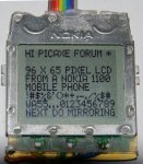
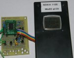
Now I have a Nokia 1100 mobile/cell phone.
Looking at the available information, the basic specs are:
Resolution: 95 x 65
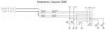
Driver chip: PCF8814 chip -- http://www.datasheets.org.uk/PCF8814*-datasheet.html
Driver chip interface: has 3-wire serial, SPI and i2c
Logic Supply: 1.7 to 3.3 Volts
Backlight: inbuilt LED
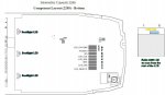
Easy to solder connections: http://sunbizhosting.co.uk/~spiral/secret files/1100lcd.html

Unfortunately it seems the Nokia connections do not use the i2c interface :(
so will progress based on the "usual" SPI type serial interface.

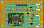
May be a while before I actually get around to assembling a demo project for this particular LCD module
At this time though that others may be interested from the viewpoint that
- it has a better resolution than the 3310 series 84x48 displays
- a check on Ebay finds more available that the 3310's
- has an inbuilt backlight through the main LCD connector
 
Last edited:

westaust55

Moderator
Nokia 1100 gLCD module - finally getting under way

Made a start tonight by dismantling the Nokia 1100 mobile/cell phone, soldering wires directly to the pads on the rear of the gLCD module (removed the sprung contacts) and patching via a 74HC245 plus using a 3V regulator to try out the display. The electrical pad spacing on the rear of the gLCD is virtually equal to that of standard ribbon cable - so quite close and worth using a magnifying glass and DMM to verify each wire as soldered into place.
Nothing more done tonight than proving that I can initialise the display whereby uncleared garbage in the RAM is shown and then invert the display plus tweaked the Vop register values for reasonable contract level.

Using the backlight LEDs hard wired to 3 Volts via approx 50 Ohms gave ample illumination - just cut away the plastic diffuser then mounts behind the gLCD and keypad and re-fit the portion which goes around the LEDs and across the rear of the gLCD module.
The backlight certainly makes readability in any ambient light level and viewing angle far easier that the Nokia 3310 and Siemens A55 displays.

There is some information out there on the Internet but, it has proven to be questionable. For example:
1. Only need a 4.7 Ohm resistor for the backlight LED's. That would result in a very high current. using 47 Ohms (ie ten times as high a value) results in a current around 15 mA which is ample.
2. Some code examples leave the CS pin permanently low whereas until I toggle it low at the start of a transmission and high after a command the gLCD would not function.
So the old adage about relying to heavily on information on the internet still applies. Much of what is out there is a clone of same data posted by sunbiz at the link given in Post 1.

Programming is a little different to the Nokia 3310 and Siemens A55 displays in so far as there is no D/C (data/Command) pin. Instead 9 bits of information are sent at a time where the first bit is the D/C bit and the remainder are the actual command or data. The extra bit can easily be handled on X1 and X2 parts within the SHIFTOUT command when sending the 8 bits of command/data. For other PICAXE chips a few extra HIGH and LOW commands will do equally as well.

From reading the LCD driver chip datasheet, the driver chips is able to flip the display vertically or horizontally and addressing in sequence can be left to right or right to left.

While many will want the commercial 128x64 glCD modules, for a simple 96 x 64/65 display the gLCD module from a Nokia 1100 (or some others in the 11xx series) and some careful soldering is an option.

More information on hardware and software aspects will be posted at a later time (busy weekend ahead) once I have prepared an interface circuit on strip board as opposed to a breadboard and tweaked some BASIC program code for PICAXE use specifically with the Nokia 1100 display.
 
Last edited:

manuka

Senior Member
An nifty quest, & with several hundred million Nokia 1100 made it'd be readily explored. (Rummage noises) - Yes- I've even got one here. FWIW a quick Google shows the "BOCHUM" version of this phone is "credited" with interesting attributes...
 

westaust55

Moderator
Nokia 1100 gLCD interface to PICAXE microcontrollers

Attached is the start of a tutorial covering the preparation, interfacing of a Nokia 1100 gLCD module to a PICAXE microcontroller.

Once I have progressed my experiments with the programming side further, I will update the tutorial to include the software to control the gLCD and display text, etc, together with any aspects and limitations/cautions that I find or deem pertinent.


EDIT: some other Nokia models with the same 96 x 65 monochrome resolution, but unchecked by myself for compatability, are:
1101, 1108, 2100, 2112, 2115, 2118, 2120, 2270, 2272, 2280, 2285, 2300, 3410, 3510, 3570, 3585, 6210, 6310, 6340, 6360, 6370, 6590, 7110, 7160, 7190

Some others have 96 x 68 but I have not collected data on the LCD's
1110, 1112, 1200, 1202, 1203
 

Attachments

Last edited:

westaust55

Moderator
Attached is part 3 of the tutorial which covers
  • the PCF9914 instruction set,
  • PCF8814 initialisation,
  • some apparent non functional commands,
  • a demo program, and
  • photos of the screen at various points during the operation of the demo program


The demo program as listed in the tutorial is all separately attached as a .bas file.


Next I will convert from a breadboard circuit to a more permanent circuit on protoboard and assembled in a plastic project box for my furture experiments.
 

Attachments

Last edited:

SAborn

Senior Member
Very good Westy.

Although the mind boggles to why you would want to mirror something. (maybe if you are addicted to standing at the mirror)

One comment to the presentation (getting picky here) would be to print the PE file to pdf in colour, so all the program text is in colour syntax as we would normally view it in PE.
It is one advantage i find with putting code in pdf files on a forum is the ability to use colour text in the pdf file.

Now all i need to do is mug someone for their phone, so i can hack their screen. (kidding of course) i still have a box of 3310's to use up yet.
 

westaust55

Moderator
Nokia 2280 96x65 LCD module

Was given a Nokia 2280 late last week.

A search found the Nokia RH-17 manual which gave the LCD pinout. which differs from the Nokia 1100.
There is no inbuilt LED's and a 1 uF capacitor is required on the Charge Pump pin (as is required for the Nokia 3310 LCD modules).

A search of the Philips/NXP site found a document that suggested they only make one LCD driver chip for the 96 x 65 resolution so tried the same demo program as for the Nokia 1100 display.
This does work to print text and for vertical mirroring (about the X-axis) but the the same command as for Nokia 1100 does not give the horizontal mirroring function.

I have cut off the piece of PCB which has the three LEDs for the LCD backlight, soldered a few wires to the LEDs (each is separately controlled from the Nokia 2280 schematic).

A potential bonus for more senior users of the 2280 LCD module over the 1100 LCD module is that for the same resolution, the active area of the display is 15% larger in width and height.

Will follow up with some specific details on connections in soon . . . .
 
Last edited:

westaust55

Moderator
Attached are diagrams for the:
  • Layout of the Nokia 2280 PCB showing the position of the 3 LCD backlight LED’s and the sequence of the connections for using the LCD with a microcontroller such as the PICAXE.
  • The portion of the schematic relevant to the LCD.
View attachment 9932


VFLASH1 is the LCD primary supply and will work with 3.3 Volts.
VIO is the IO signal voltage level and can be ties to VFlash

Note that a 1 uF tantalum type capacitor from the LCD-Charge_pump (for Vlcd) pad to ground is mandatory for the Nokia 2280 gLCD module but not required (already incorporated) for the Nokia 1100 gLCD module,
The other capacitors (ceramic or polyester types will work) are primarily for noise filtering and in fact my gLCD is working without any more than a 10 uF tantalum on the 3.3 Volt supply.
 

Attachments

Last edited:

westaust55

Moderator
Nokia 2280 gLCD

Attached is a photo of the Nokia 2280 gLCD display when using the same demo program as posted above for the Nokia 1100.
Note the additional wiring at the bottom for the backlight LEDs (using the mid part of the Nokia PCB upon which the LEDs are mounted).

And Yes, the message on the screen still indicates Nokia 1100 but it is in fact a Nokia 2280 display :)
 

Attachments

Svejk

Senior Member
Thanks Westaust55.

I have a 2280 gLCD ready to play but I can't read the caps values. Can you add a descriptive of values, please?

Regards,
S
 

westaust55

Moderator
The capacitor values are:
Code:
Pin  Left side  Right side
 6   100 nF        2n2 F
 7   100 nF      100 nF
 8      1 uF       none
As mentioned in the text, the capacitors on pins 6 and 7 are more for noise filtering and I have experimented successfully with 100 nF to both pins and no cap on these pins (but still a tantalum cap on the output of the 3V3 voltage regulator.
 

westaust55

Moderator
I have also found another datasheet for an Philips OM6208 96x65 gLCD driver chip.
Almost the same as the PCF8814 but whereare the PCF8814 is monochrome (1-bit resolution) as are the 1100 and 2280 displays, the OM6208 is 4 levels of grey scale.

With the Nokia 2280 gLCD I have again tried the BRS command and it is working.
The top 4 blocks of 8 lines (32 pixels high) are swapped with the lower 4 full blocks (32 pixels) but also inverted at the same time.

So if we add in the two extra subroutines:
Code:
NoBRS:
	Value = $E0	   ; normal display with dark chars on light background
	GOSUB CommandToLCD
	RETURN
;----------------------------------------------------
BRSOn:
	Value = $E1	   ; normal display with dark chars on light background
	GOSUB CommandToLCD
	RETURN
;----------------------------------------------------
And then call two subroutines:
Code:
	GOSUB BRSOn
	GOSUB VertMirror
then in terms of text, the top 4 rows of 8 pixel high characters are swapped with the lower 4 rows of characters and they are correctly orientated to be read.

In character line format the standard/normal presentation:


Pixel row 0
Pixel row 1
Pixel row 2
Pixel row 3
Pixel row 4
Pixel row 5
:
:
:
Pixel row 61
Pixel row 62
Pixel row 63
Pixel row 64

becomes

Pixel row 32
Pixel row 33
Pixel row 34
Pixel row 35
Pixel row 36
Pixel row 37
Pixel row 38
:
:
Pixel row 64
Pixel row 65
:
:

Pixel row 0
Pixel row 1
Pixel row 2
Pixel row 3
Pixel row 4
Pixel row 5
:
:
Pixel row 30
Pixel row 31
Pixel row 32

Will have to go back and recheck this functionality on the Nokia 1100 gLCD as first attempts did not see any change using the "BRS" command/function.

Unfortunately the above does not quite line up with our usual 8-pixel high character rows.
If you think of it in terms of character lines the first line is pushed down 4 lines but as there are 65 rows of pixels, the top rown form the next line is placed in the very bottom pixel row with the rest of the display rolling over and continuing at the top of the gLCD display.

EDIT:
Have rechecked the Nokia 1100 and the BRS feature definitely does not function with the Nokia 1100 as had previously been identified but does work as described above for the Nokia 2280.
 
Last edited:

westaust55

Moderator
Last night I assembled a PICAXE to Nokia 1100 gLCD interface circuit on a prototyping board.
I tried a 1/2 sized Gadget Gangster board which was large enough but did involve a few more links compared to the proto boards I usually use due to absence of traces for a double power supply bus around the board.

Compared to the bread-boarded version, I elected to run the backlight LEDs direct form the 5 Volt supply which reduces the current through the LP2950 3.0 Volt regulator.
This also necessitated using two transistors as opposed to the original one transistor for the backlight driver circuit.

I have updated the parts 2 and 3 of the demo/basic tutorial on page 1 of this thread to reflect the changes including the embedded schematic diagram.

I have used a 150 Ohm resistor in series with the gLCD backlight LED pad connection. This limits the current to around 18 mA which is about as low as the current can go for the display to be readable in the dark.

Next I will mount the interface into a plastic box using my usual DA-15 plug type connector for further experiments via my main PICAXE Experimenters box.
Considering the Nokia 1100 schematic show a 4.7 Ohm series resistor for a ~3V supply (and the Nokia 1100 circuit does not have a PWM chip as the Nokia 2280 does), this equates to a current of 144 mA. So albeit without a datasheet for the backlight LED’s there is seemingly some capability for greater LED current.


Attached to this post are:
1. the layout produced with PEBBLE for the circuit I used, based upon the Gadget Gangster ½-sized prototyping board, and
2. A photo of the interface board and the gLCD module prior to mounting the interface into a plastic box.

For the gLCD, I have also retained and mounted the clear protective screen from the original Nokia case in front of the LCD and mounted the entire gLCD assembly using some of the Nokia screws and a 3mm long nylon spacer at each corner of the display.
 

Attachments

Last edited:

westaust55

Moderator
To close off on the Nokia 1100 and 2280 gLCD modules, attached are:

1. A PICAXE to Nokia 2280 gLCD interface schematic which takes into account the need for the 1 uF capacitor on pin 8 of the gLCD and separate drive for the backlight LEDs if salvaged from the original PCB.

2. A PICAXE demo program to show the BRS (Bottom Row Swap) and driving the backlights for the 2280 based gLCD
(Had to provide as an attachment due to text length if embedded in the post).
 

Attachments

Last edited:

Flitch

New Member
Hello westaust55,

I got my hands on nookia 1100 display (my friend found it in drawer, and he will give it to me in next few days ;D) , now i need your help.
first some questions:p
1. is same example code working on 20M2
2. why freq 8MHz, is screen malfunctioning at faster rate?
3. is there any other way to interface without 74hc245 or 74lvc245, if so what is it?
4. adding graphic? how hard is it? basicaly horizontal /vertical and even angled lines is all i need (got external EEPROMS)
 

mealyoja

New Member
Have someone use Nokia 1101 Display for a project or anybody knows what type of controller it's used for this type of Display? I know that for some nokia was used controller from Epson, Philips or samsung, but for Nokia 1101 display I've didn't found any datasheet.
Someone can help?
Regards
 
Last edited:

Flitch

New Member
hey westaust55 could you posibly check my code? i am using 20m2 so i had to modify spiout comand to a subroutine for 20m2, would be nice if you tell me if that will do the job or what i have to fix

View attachment 1100 code.bas

also text version:
Code:
#PICAXE 20m2
#Terminal 9600
; #NO_DATA
;Define the IO pins for outputs to the gLCD
SYMBOL SCLK = 1
SYMBOL SDA = 2
SYMBOL LED = 0
SYMBOL CS = 3
SYMBOL RES = 4
;Define constants for the D/C command
SYMBOL LCD_C = $00
SYMBOL LCD_D = $80
;Define alias names for used variables
SYMBOL value = b0
SYMBOL width = b1
SYMBOL pointer = b2
SYMBOL X = b3
SYMBOL Y = b4
SYMBOL eeprom_addr = b5
SYMBOL Loop1 = b10
SYMBOL loop3 = b11
symbol counter = b6	' variable used during loop
symbol mask = w4 		' bit masking variable
symbol var_out = w6	' data variable used during shiftout
symbol bits = b7		' number of bits
symbol MSBvalue = b15	' MSBvalue (=128 for 8 bits, 512 for 10 bits, 2048 for 12 bits)
;
' ========================================================================


' ========================================================================
;===============================================================

; perform initialisation
; in reality a bit too slow for the gLCD in terms of resetting but does work
Init:
SETFREQ m8
LOW RES
LOW CS
PAUSE 50
HIGH RES
GOSUB InitLCD
;===============================================================

Main:
; Now a demo in "Normal" mode with no mirroring
GOSUB BliteOn ; turn the backlight LEDs on
GOSUB AllPxOn ; first turn on all pixels as a demo
PAUSE 4000 ; a delay just so the user can see what is happening
GOSUB BliteOF ; turn of the backlight LEDs
PAUSE 4000 ; a delay just so the user can see what is happening
GOSUB BliteOn ; and finally turn the backlight LEDs on again
GOSUB BlkonWht ; then revert to the normal dark image on light background
GOSUB GoToHome ; move "cursor to x=0 and y = 0
FOR pointer = 0 TO 16
LOOKUP pointer,("HI PICAXE FORUM *"),value
GOSUB ValueToLCD ; send data to the gLCD
NEXT
PAUSE 2000 ; just a delay to give user time to see what is happening
X=0 ; now move block 2 = third line for "normal" text
Y=2
GOSUB GotoXY
FOR pointer = 0 TO 16
LookUp pointer,("96 X 65 PIXEL LCD"),value
GOSUB ValueToLCD
NEXT
X=0
Y=3
GOSUB GotoXY
FOR pointer = 0 TO 16
LookUp pointer,("FROM A NOKIA 1100"),value
GOSUB ValueToLCD
NEXT
X=0
Y=4
GOSUB GotoXY
FOR pointer = 0 TO 16
LookUp pointer,("MOBILE PHONE "),value
GOSUB ValueToLCD
NEXT
PAUSE 2000
X=0
Y=5
GOSUB GotoXY
FOR pointer = 0 TO 16
LookUp pointer,("!#$%&'()*+,-./%$#"),value
GOSUB ValueToLCD
NEXT
X=0
Y=6
GOSUB GotoXY
FOR pointer = 0 TO 16
LookUp pointer,("WA55...0123456789"), value
GOSUB ValueToLCD
NEXT
X=0 ; displyaing text in the last full block/line
Y=7
GOSUB GotoXY
FOR pointer = 0 TO 16
LookUp pointer,("NEXT DO MIRRORING"), value
GOSUB ValueToLCD
NEXT
PAUSE 6000 ; longer wait giving time to read all
GOSUB Invert ; then invert the display for white text on black
PAUSE 6000
GOSUB Normal ; return to "normal" with black text on white
; mirror Y-axis (about the X-axis) - mirrors existing and new immediately
GOSUB VertMirror
PAUSE 6000 ; wait a while so user can see result
; stop mirror Y-axis (about the X-axis) - now normal view again
GOSUB NoVertMirr
PAUSE 6000 ; wait a while so user can see result
GOSUB ClearFast ; clear the entire display
GOSUB GoToHome
FOR pointer = 0 TO 16
LOOKUP pointer,("HI PICAXE FORUM *"),value
GOSUB ValueToLCD
NEXT
PAUSE 2000
X=0
Y=1
GOSUB GotoXY
FOR pointer = 0 TO 16
LookUp pointer,("FROM WESTAUST55 *"),value
GOSUB ValueToLCD
NEXT
X=0
Y=3
GOSUB GotoXY
FOR pointer = 0 TO 16
LookUp pointer,("NEXT HORIZ MIRROR"),value
GOSUB ValueToLCD
NEXT
; Invert screen in horizontal axis - does not affect existing only new data
GOSUB HorizMirror
X=0
Y=4
GOSUB GotoXY
FOR pointer = 0 TO 16
LookUp pointer,("THIS IS BACKWARD "),value
GOSUB ValueToLCD
NEXT
PAUSE 2000
X=0
Y=5
GOSUB GotoXY
FOR pointer = 0 TO 16
LookUp pointer,("WA55 0123456789.."),value
GOSUB ValueToLCD
NEXT
; Back to normal screen in horizontal axis - does not affect existing only new data
GOSUB NoHorizMirr
X=0
Y=6
GOSUB GotoXY
FOR pointer = 0 TO 16
LookUp pointer,("WA55...0123456789"), value
GOSUB ValueToLCD
NEXT
X=0
Y=7
GOSUB GotoXY
FOR pointer = 0 TO 16
LookUp pointer,("DEMO IS ALL DONE"), value
GOSUB ValueToLCD
NEXT
PAUSE 6000
GOSUB Invert
PAUSE 6000
GOSUB Normal
PAUSE 6000
GOSUB DispOff ; turn off the display
pause 6000
GOSUB BliteOf
STOP
END
;===============================================================

; SUBROUTINES
;---------------------------------------------------------------------
;
;========================================================================
; ***** Shiftout MSB first *****
shiftout_MSBFirst:
for counter = 1 to bits				;number of bits
	mask = var_out & MSBvalue		;mask MSB
	high SDA					;data high
	if mask = 0 then skipMSB
	low SDA					;data low
skipMSB: 
	pulsout SCLK,1				;pulse clock for 10us
	var_out = var_out * 2			;shift variable left for MSB
	next counter
return
' ***** Sample symbol definitions *****
;========================================================================


InitLCD:
LOW SCLK
LOW SDA
LOW LED
LOW CS
LOW RES
PAUSE 50
HIGH RES
HIGH CS
Value=$22 ; Write to the VOP register
GOSUB CommandToLCD ; transmit To serial LCD module
Value=$90 ; NOTE max allowed is 9V
GOSUB CommandToLCD ; transmit To serial LCD module
Value=$2F ; Power control set (charge pump on/off)
GOSUB CommandToLCD ; transmit To serial LCD module
Value=$40 ; set start row address = 0
GOSUB CommandToLCD ; transmit To serial LCD module
GOSUB BlkonWht
GOSUB Disp_On
GOSUB ClearFast
RETURN
;----------------------------------------------------
ClearFast:
GOSUB GoToHome
LOW SDA
; HIGH DC ; Write data mode
LOW CS
FOR Loop1 = 0 TO 95 ; 96 pixels wide
FOR loop3 = 0 TO 8 ; 9 banks high
let bits = 1
let var_out = LCD_D
let MSBvalue = 1
gosub shiftout_MSBFirst
let bits = 8
let var_out = $00
let MSBvalue = 128
gosub shiftout_MSBFirst
NEXT loop3
NEXT Loop1
GOSUB GoToHome
RETURN
;----------------------------------------------------
GoToHome:
X = 0
Y = 0
GotoXY:
Value = X AND $0F ; lower part of X address
GOSUB CommandToLCD
Value = X / $10 AND $07 OR $10 ; upper part of X address
GOSUB CommandToLCD
Value = Y AND $0F OR $B0 ; Y address command
GOSUB CommandToLCD
RETURN
;----------------------------------------------------
; Send an instruction to the gLCD preceded by a "1" as the command flag
CommandToLCD:
LOW CS
let bits = 1
let var_out = LCD_C
let MSBvalue = 1
gosub shiftout_MSBFirst
let bits = 8
let var_out = value
let MSBvalue = 128
gosub shiftout_MSBFirst
HIGH CS
RETURN
;----------------------------------------------------
NoHorizMirr:
Value = $A0 ; subsequent data output is left to right
GOSUB CommandToLCD
RETURN
;----------------------------------------------------
HorizMirror:
Value = $A1 ; subsequent data output is right to left
GOSUB CommandToLCD
RETURN
;----------------------------------------------------
BlkonWht:
Value = $A4 ; turn off the All Pixels On mode for normal display
GOSUB CommandToLCD
RETURN
;----------------------------------------------------
AllPxOn:
Value = $A5 ; turn on all the display All Pixels for black image
GOSUB CommandToLCD
RETURN
;----------------------------------------------------
Normal:
Value = $A6 ; normal display with dark chars on light background
GOSUB CommandToLCD
RETURN
;----------------------------------------------------
Invert:
Value = $A7 ; invert the display light chars on dark background
GOSUB CommandToLCD
RETURN
;----------------------------------------------------
LsbTop:
Value = $A8 ; data dispalyed with the lsb at top of blocks
GOSUB CommandToLCD
RETURN
;----------------------------------------------------
MsbTop:
Value = $A9 ; data dispalyed with the msb at top of blocks
GOSUB CommandToLCD
RETURN
;----------------------------------------------------
DispOff:
Value = $AE ; turn the display off
GOSUB CommandToLCD
RETURN
;----------------------------------------------------
Disp_On:
Value = $AF ; turn the display on
GOSUB CommandToLCD
RETURN
;----------------------------------------------------
NoVertMirr:
Value = $C0 ; normal display with dark chars on light background
GOSUB CommandToLCD
RETURN
;----------------------------------------------------
VertMirror:
Value = $C8 ; normal display with dark chars on light background
GOSUB CommandToLCD
RETURN
;----------------------------------------------------
BLiteOn:
High LED ; Turn on the LED backlight
RETURN
;----------------------------------------------------
BLiteOf:
LOW LED ; Turn on the LED backlight
RETURN
;----------------------------------------------------
; this routine takes as ASCII character and reads EEPROM for the bitmap data
; if the character is narrow the width allowed is reduced to improve chars/line
ValueToLCD:
eeprom_addr=0
IF Value>32 and Value <58 then ; test if upper case letter
eeprom_addr=Value-33
eeprom_addr=eeprom_addr*5+130
ELSEIF Value>64 and Value <91 then ; test if a lower case latter
eeprom_addr=Value-65
eeprom_addr=eeprom_addr*5
ELSEIF Value=32 then ; test if character is a space
Value = 0
GOSUB DataToLCD
GOSUB DataToLCD
GOSUB DataToLCD
GOSUB DataToLCD
ENDIF
IF Value=0 then
RETURN
ENDIF
width = 4
read eeprom_addr, Value
IF value = 0 then ; found a narrow character
width = 2
inc eeprom_addr
ENDIF
FOR Loop1 = 0 TO width
READ eeprom_addr, Value
INC eeprom_addr
GOSUB DataToLCD
NEXT Loop1
value = 0
GOSUB DataToLCD ; put a 1 bit space after each character for clarity
RETURN
;----------------------------------------------------
; routine to send bitmap data bytes to the gLCD preceded by a "0" as the data flag
DataToLCD:
LOW CS
let bits = 1
let var_out = LCD_C
let MSBvalue = 1
gosub shiftout_MSBFirst
let bits = 8
let var_out = value
let MSBvalue = 128
gosub shiftout_MSBFirst
HIGH CS
RETURN
;----------------------------------------------------
; Following is the bitmap....
 

westaust55

Moderator
Generally looks okay but think the line
If Mask = 0 then skipmsb
Should be
If mask = 1 then skipmsb

Have you tried it to see it it works as you had it?
 
Top