Using the Nokia 128x128 4096 colour gLCD with PICAXE chips

westaust55

Moderator
I have now started on a new path with old mobile phone gLCD modules.

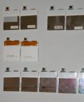
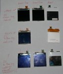
Past work has been based on monochrome displays but having been given a handful of faulty Nokia 6610 mobile phones I have started to interface and do some programming with these. One had a corroded LCD connector and a couple of others are suspect but some have working LCD modules).

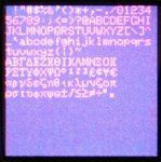
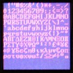
The display is 128 x 128 RGB with 4096 colours and a 256 colour mode as well.

The connectors are very small and in reality little chance of soldering direct to the connector so some form of breakout board is essential. In my case, and as presented in the attached first part of the guide, I used the actual Nokia board after removing all but some essential components and a couple of larger ICs.

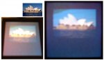
I have a commenced some programming and have displays with the Epson (green flexible circuit to connector) working but am still at this moment experimenting with set up parameters to determine the best setting.
There is some code out there on the Internet via Sparkfun and other websites for AVR micros and written in C but I have found the setting not to match the controller chip datasheets requirements.

More will follow later.
 

Attachments

Last edited:

westaust55

Moderator
The attached pdf file provides some further level of details for the Nokia 6610 PCB layout and also some schematics based upon the use of the part of the Nokia PCB as opposed to a commercial breakout board.

I do have some components on order from Futurlec to build an alternate DC-DC step-up circuit for the Backlight for those who have the gLCD module but no PCB which I will incorporate into the document at a later date.

EDIT (9/1/2012):The original two schematic files were embedded jpeg files but I noted that the diagrams were very blurred around the test.
I have created new pdf files but due to the resultant size have split part 2 into sections a and b.
In addition I have added a third schematic for those who may use other methods for connecting to the Nokia 6610 and similar gLCD modules and be in need of a backlight supply circuit. The schematic is based upon the MC34063 DC-DC step-up/step-down/Inverter chip which is available from Altronics in Australia or Futurlec for those worldwide.

EDIT (10/1/2012): I have now added PCB layouts for the Nokia 6610i (a later version of the 6610 which included a camera).
I have tonight cut the PCB on a 6610i at the same location as shown on the diagrams and the Chip Select line is still intact :)
 

Attachments

Last edited:

westaust55

Moderator
I have now sorted out what I perceived to be the best initialisation setting for the Nokia6100/6610 and similar gLCD modules for use with those having the EPSON S1D15G00 controller chips to operate in 256 colour (8-bit RRR-GGG-BB colour mode).

The attached pdf file provides the EPSON controller chip instructions, an initialisation subroutine, a demo program and a photo showing what the display looks like when the 256 colour demo program is run.

I will soon look at the subroutine necessary to display a standard 5x8 pixel character sized font.

Certainly one advantage with these displays compared with the monochrome gLCDs is that each pixel is addressed separately so when “drawing”/plotting one pixel there is no need to consider the adjoining pixels.
However a downside is that the code for plotting a font will tentatively be more complex as we cannot just feeds 5 bytes of data to the gLCD.

Most of the working displays that I have extracted from faulty Nokia 6610’s I have obtained use the EPSON controller. I do have a couple with the Philips controller and if they in fact work will post some equivalent information at a much later date for these as well.


I will post some actual PICAXE program code as a .bas file once I have some font plotting subroutine up and running.

EDIT: Part3 updated with some corrections plus information for gLCD's with Philips controller chips added

EDIT2 (31-1-2012): Part3 updated with further introduction to the controller chips, some corrections plus information for gLCD's with Leadis LDS176 controller chips added
 

Attachments

Last edited:

westaust55

Moderator
Using the Nokia 6610 and similar gLCD with PICAXE - text display

I have written some PICAXE BASIC code to display test on the gLCD module.
Not that difficult to prepare the code but partially for speed and partially for ease of programming needs 8 bytes per character, so holding font data in PICAXE internal EEPROM only allows 32 characters.

See attached photo. Some text colours versus background colours obvious photograph better but the white on blue is actually quite easy to read in reality.

Also regenerated the attachement at post 2 since the text on the schematics was rather fuzzy but new file although much clearer was larger so have split into 2 parts.
 

Attachments

westaust55

Moderator
Managed to get my hands on some faulty 6610i mobile phones today (the "i" variant has an inbuilt camera).
Armed with the code RM-37 (from inside the phone) and have found the schematics.
The part of the circuit of interest and test pad locations are unchanged but some of the backlight DC-DC step-up circuit components are on the same side of the PCB as the gLCD in the 6610i.

Have not tried any of the actual LCDs yet but did dismantle one phone cut off the bottom third at the same point as per my earlier example and the circuits between the test pads and 10-pin Hi-Rose connector are still intact - which is a good sign.
Have not yet drilled a hole for wire pass through and because the DC-DC step-up IC is now on the same side as the gLCD will need to consider getting an extra wire through for the Backlight Enable signal.

I have added the relevant diagrams for the 6610i PBC layout identifying components to keep into the Part 2a pdf file attached to post 3.

The usual 5x7 character size is barely readable, so tonight as a check I added some font data for a few characters in 7x9 pixel size (still with 1 blank pixel to right and bottom) and these are a lot more easily read.
My main PICAXE program routine for sending the data for a 256 colour character did not require any changes, just added an alternate font definition entry point to give the width and height data.
Noting that the Nokia specs for the 6610/6610i state the display is 8 lines so they are in fact using a 10x16 pixel font.

Still to write some code to initialise the EPSON controller into 12-bit (4096) colour mode although I envisiage that this mode is likely better suited to display of converted bmp images that for usual text and simple graphics such as wave forms, boxes, circles etc.

I note that the first phone dismanted from the new lot (of faulty phones) has a Philips controller so hopefully at least one of those is also working to enable defining initialisation data and some basic routines for the Philips controller as well.
 

westaust55

Moderator
I have been working on some basic graphic routines which are nearing completion to:
1. Plot/set any point
2. Draw a line between two points
3. Draw a filled or unfilled box
4. Draw a circle ( and maybe also a equal sided diamond shape)
As mentioned certainly much easier when the maths do not have to consider 7 adjoining pixels as is the case with the monochrome gLCD from mobile phones.
Have also put together the data for an 8x10 font (actual characters 7 x 9) which are more visible/readable than the 6x8 (5x7 char size) font – at least for older eyes.

Last night I dismantled the rest of the faulty phone I was given. Of the total phones received, 90% use the EPSON controller and just a few with the Philips controller.
As soon as I have wrapped up my initial experiments will look at the initialisation process for the Philips controller provided at least one of them is functional (have only tested 4 of those with EPRSON controller to date).

Parts from Futurlec have arrived yesterday, including some DC-DC converter IC’s, so I will test my as yet unbuilt circuit for those with a gLCD but no PCB for the backlight supply.
 

westaust55

Moderator
I have expanded/updated the Part 3 pdf of the document at post 4.

Attached to this post is the PICAXE BASIC program which contains the various subroutines as mentioned in post 7 and a demo Main program section to display the various text and other images as per the photos in part 3 of my "tutorial".

I highlight that all of these routines are for operation in the 256 colour mode. The 4096 colour mode required different routines to pass 12-bits or 2 bytes of colour data in each routine and also requires changes to the gLCD initialisation routine (something for another day).

I have also prepared a file with the data for the full 6x8 (5x7 character size) and 8x10 (7x9 char size) which I will separately post in the near future for those who have external EEPROMs to hold the full data for the two fonts. The two fonts with 96 characters each ($20 to $7F) requires just under 2 kBytes.
I may add a few more characters first such as the greek alphabet and a few other symbols in line with my past work for the Siemens A55 monochromes GLCD first, so please be patient for a few more days.

Then my next step will be to see if any of the gLCD's with the Philips driver/controller chips that I have extracted from faulty mobile phones are working and repeat much the same exercise.
 

Attachments

John West

Senior Member
Fascinating reading, Westy. Great graphics on these small displays. Fun stuff. I need to find a few of these phones to play with now that you've done all the hard work.
 

westaust55

Moderator
6x8 fontset (small) for use with the Nokia 128x128 gLCD modules

Attached are two PICAXE programs:
1. A program to write the data for a 160 character 6x8 pixel (5x7 char size plus inter-character spaces) which includes the more regular font of 96 characters, the Greek alphabet comprising 48 characters for upper and lower case, and some various other symbols such as:
  • +/- <= >= not=
  • superscript 1,2,3 for powers,
  • square-root, degree
  • UK Pound, cents, Yen and Euro symbols


2. A slightly modified version of the program posted above which will read the fontset data from an external EEPROM which is defined with slave address % 10100000 but this can easily be changed.
Because I already have some other data permanently stored in my EEPROM at the nominated slave address I have started this data at address/location $0400 but again this is easily changed.


In this case for the posted 6x8 font, I already had a fontset for the Greek alphabet and the extra symbols drawn up in Excel from my earlier work with monochrome displays, The Excel data just needed some reworking which was relatively easy and I even set up Excel to write the data including text for commands including pause statements and commas etc into a .csv file which I could open with notepad and cut & paste directly into the Programming Editor to minimise time.


For larger fonsets, I firstly need to create another excel spreadsheet for the larger character size in which to draw the characters and have Excel write the data into the .csv file format.


EDIT (31/1/2012):
The posted code sets the "Electronic Volume" / contrast settings to $20 and $01 respectively.
By changing these to $10 and $02/$03 respectively changes to the "Contrast" settings are far more distinct.
See the lines:
Code:
	value = $81 : GOSUB SendCmd	; Electronic Volume (Contrast) Control Command (takes 2 byte parameters) 
	value = [B]$20 [/B]: GOSUB SendData	; lower 6 bits used : V1 volume/contrast value 'alpha' $00 to $3F is valid
	value = [B]$01[/B] : GOSUB SendData	; lower 3 bits used : 1+ Rb/Ra = specifies internal resistance ratio
 

Attachments

Last edited:

westaust55

Moderator
Nokia 128x128 colour gLCD - 8x10 pixel font and demo code

Attached are:
The demo program with routines with some extra lines of program to demo the slightly larger 8x10 font - visible for me at least ;)
also a program to install the 160 character 8x10 font into an external EEPROM (takes 1.75 kBytes of EEPROM space).
 

Attachments

Last edited:

westaust55

Moderator
Fonts for the Nokia 6610 &amp; clone 128x128 ( actual 130x130) gLCD modules

I have attached a couple of photos showing the two fontsets.
The first shows the 6x8 font size and the second the 8x10 font size.

Both images have a extra pixel allowed (by selection of the x,y positioning parameters for each line) for clarity sinc the fonts have decenders on some characters.

The 6x8 font size allows 14 rows (or 16 without a extra pixel of spacing) of 21 characters but your eye sight needs to be good

The 8x10 font size allows 11 rows (or 12 without a extra pixel of spacing) of 16 characters and in the real world, is visually better.

On my 19" LCD PC monitor, the thumbnails within this post are roughly the actual size of the displays
 

Attachments

westaust55

Moderator
Nokia 128x128 colour gLCDs - with PHILIPS controller chip

Attached is a PICAXE program to provide the same routines and demonstration as the EPSON driver based program in post 11 but now for the PHILIPS PCF8833 driver chips controlled gLCD's. It again requires the same two font set files as the EPSON based gLCD to be saved into external EEPROM.

In addition I have earlier updated the "tutorial" Part 1 (at post 1) and also to reflect information and program changes for the PHILIPS controller based gLCD modules the Part3 section (at post 4) has been updated.
 

Attachments

westaust55

Moderator
Having now achieved working code for the EPSON S1D15G00 and PHILIPS PCF8833 LCD controllers, I started to check out the various LCD modules I had retrieved from Nokia phones.

The lead to the discovery that there is a third type. :eek:

Not only that, but the often quoted rules for green flex circuits for EPSON and brown flex circuits for Philips is not 100% correct.
I have two LCD's with brown flex circuits to the connectors but are using EPSON S1D15G00 controllers and working.

An observation or two is:
1. Epson S1D15G00 based LCDs have a silver backing and the first characters on the top row of the two rows of digits are "6P....."
2. The Philips PCF8833 based LCDs have a white backing and the first characters on the top row of the two rows of digits are "7P....."
3. All of the controller with the above two controller chips have a red circle on the rear on or near the rear labelling

Additionally there are more controllers that make be used as follows- at least for the clone LCD market:
1. EPSON S1G15D10. This has the same command set as the S1G15D00 but two commands for initialisation each take an extra parameter.
2. There is a controller by Leadis - LDS176 which from a brief review of the datasheet has the same command values and functionality as the Philips PFC8833.

Finally, I have a number of gLCD modules taken from 6610i mobile phones only (not the earlier 6610 models) with:
- a silver backing and a green flexible circuit to the connector.
- a darker brown copper circuit traces and have some SMD components including the top two backlight LEDs mounted onto the flexible circuit.
- A green dot to the right of the text markings
- Consistent first row text of UG13D004&#8230; followed by varying characters
- Consistent second row test of &#8220;4850835 P&#8221; some then followed by a &#8220;C&#8221;
I have seen a few references to these LCDs by these marking on internet sites such as on Instructables but need to delve deeper.

Further work to identify these third type of LCD controller will need to wait as I will be working away for a while with no PC/laptop access.

In the attached photo;
  • the top row are EPSON S1G15D00 based modules
  • the seconds row are Philips PCF8833 based modules
  • the bottom row are yet to be identified and initialisation determined
 

Attachments

Last edited:

westaust55

Moderator
Determining a third type of Nokia Phone gLCD controller chip . . . .

Back after a weeks sojourn away from home and looking at trying to identify the third type of module taken from Nokia 6610i mobile phones.

I have tried code based upon the EPSON S1D15G00, the EPSON S1D15G10, and the Philips PCF8833 controller chips without success today using various Vlcd voltage and contrast levels.
A further observation is the size of the controller chips as visible from the front (viewing side) of the modules.

1. For the EPSON controllers irrespective of flex circuit colour the gLCD controller is dark blue-green and approx 24 mm in length (and ~2.8 mm high)
EPSON datasheets do not indicate the actual chips size.

2. For the Philips controllers the IC is silver-grey in colour and approximately 19 mm in length ( and ~ 2 mm high).
Interestingly, the Philips PCF8833 datasheet indicates the chips is 22.93 x 2.34 mm

3. All of the third type gLCD module type have a controller IC that is dark grey in colour and approx 19 mm in length and . . . ~2.8 mm in height.
I currently doubt that it is the Leadis chip (LDS176) which is supposed to have a command set identical to the Philips PCF8833 (will recheck that datasheet tomorrow) and a chip size of 20.5 x 1.6 mm.
But then again, neither do the Philips chips do not physically match the datasheet.
One person on Instructables website, more by inference than specific statement, suggests they managed to get the third gLCD module with the same rear ID working using the Philips initialisation.
At this time it is necessary to do some further research but doubt I have 6 of these all faulty when 10 out of 11 others all work correctly from faulty phones (the 11th had corrosion damage to the connector).

EDIT:
Okay, decided to read the Leadis LDS176 datasheet again and while predominantly the same as the Philips PCF8833, when it comes to the setting of voltages for Vlcd and contrast control is different and uses a scheme more akin to the EPSON controller chips. With a few lines of changes to the Philips Initialisation, I have one of the third group of gLCD modules working. :)
More later, once I have tuned the settings and prepared a command reference table for the Leadis LDS176 chip.

This is contrary to statements on various websites and in other Nokia LCD articles which are along the lines:
The major irritant in using this display is identifying the graphics controller; there are two possibilities (Epson S1D15G00 or Philips PCF8833). The LCD display sold by the German Web Shop Jelu has a Leadis LDS176 controller but it is 100% compatible with the Philips PCF8833)
.
 

Attachments

Last edited:

westaust55

Moderator
Using the Nokia 128x128 4096 colour gLCD with PICAXE chips - with Leadis LDS176 chips

For those who are fortunate enough :rolleyes: to have a Nokia 128x128 (130x130) colour gLCD from a Nokia mobile phone using the LEADIS LDS176 controller chip,
the atatched program will provide the same functionality as those already posted for the EPSON and PHILIPS controllers.

In addition, I have updated part 3 of the "tutorial" for the use of the Nokia 128x128 gLCD modules back at post 4.
This now includes details for the Leadis controller chip commands, a revised intro to section 4 covering controller identification, plus a few minor corrections.
 

Attachments

westaust55

Moderator
It is possible to save images in external EEPROM or with some other medium (e.g. a 4D System udrive module with micro-SD memory card)
While many demonstrations on You-tube and elsewhere may be using and promote the 12-bit mode and displaying full 130x130 pixel images keep in mind that this does take a lot of storage space to hold one image. A single image in 12-bit mode and sized 130 x 130 pixels required 24.76 kbytes of data!

Using the routines I have developed and posted thus far in this thread, we can use the 8-bit (256 colour) mode and with some loss of colour display smaller images using external EEPROM.
As an example, I generated the data for an 8-bit 100 x 67 pixel image of an Australian icon and that still requires 6.54 kbytes of storage even though it occupies only approx 40% of the gLCD area.

I found a small (22 kbyte) program on the internet that will convert a bmp image file to the required RGB8 data file. Even then it is still necessary to wrap some code around that data to pre-write the data to an external EEPROM. Before you run the BMP2RGB8 program you must first use some form of paint program to resize the image to the desired size and save as a .bmp format file (Paintshop Pro, for example, will do that).

I have attached the bmp to RGB8 program (22 kbyte executable). Start the program and browse to select your bmp image file. It will create the data in hex format which you can cut and past into the PICAXE programming editor.
In addition to adding commands [ eg HI2COUT, EEPROM, Locn ($data) ] to the resultant data lines you need to ensure the data is in 64 bytes per line to prevent wrap around due to paging in the 24LC series (and other) external EEPROMS.

The PICAXE program code that will then display that image on the gLCD will be along the lines of the following code snipped that can be inserted into the Main: program section/loop for your program.

Code:
; optional to clear the screen first or just draw over the top of other graphics
; comment/remark out these two line to just draw over top of existing display image
	colour = Black			; set the initial "background" colour for clearing	
	GOSUB ClearLCD			; clear the LCD to black colour

; load an 8-bit 100x67 pixel image from external EEPROM to the gLCD
	x = 16 : width = 100		; define the x-axis start and image width
	y = 16 : height = 67  		; define the y-axis start and image height
	GOSUB GotoXY			; set the x and y axis data
	
	EEbase = $1000			; define start address in external EEPROM for image data
	index2 = width * height + EEbase - 1 ; define the end address for the image data
	
	value = $5C : GOSUB SendCmd	; command to start writing data to the gLCD RAM 
	FOR EEAddr = EEbase TO index2	; for each image pixel fetch the data from EEPROM and write to the gLCD
		HI2CIN EEAddr, (value)
		GOSUB SendData   ; 	for faster drawing, could use  -- > SHIFTOUT SCLK, SDA, MSBFirst_L, (LCD_D/1, value/8)
	NEXT
	value = $5C : GOSUB SendCmd	; send a NOP to exit from gLCD RAM writing mode - not essential but good practice
  	
	DO
	LOOP	; loop forever
	END
Maybe tonight I will post some program files to allow others to see the work involved and what the final data will look like to use PICAXE programs to pre-load the image data into an external EEPROM.
 

Attachments

Last edited:

westaust55

Moderator
Attached is a zip file containing three PICAXE BASIC programs to store the data into an external EEPROM (addr = %10100000) which can be then read from the EEPROM and written to the Nokia gLCD module using the code snippet given in the post above.

Also a composite image showing the original image file at 100x67 pixels and a couple of (unfortunately) low quality photos of the display showing the same image in 256 colour mode. It does however look far better than the camera indicates.
 

Attachments

Last edited:

westaust55

Moderator
In the code snippet posted in post 17 above, I included as a remark an alternate program line to speed up reading from EEPROM and display of an image.

I can report that using that line to reduce the time associated with the GOSUB and RETURN commands speeds up getting the image onto the gLCD by 25%.

Unlike clearing the screen and filling a rectangle/box routine I have developed where using multiple bytes in a single write/shift sequence can be used with any extra data just wrapping around, this cannot be done in the same simple manner with an image as the extra data will corrupt the top-left corner of the display. It would be possible however to read in from EEPROM and write multiple bytes to the gLCD as long as we take care to ensure the data written stops at the correct point.

A test reading 2 bytes from EEPROM at a time and writing the two to the gLCD then at the end fetch and write any odd byte reduced the time compared to the original duration to display the image by 45%.

The revised code snippet I used is:
Code:
; load an 8-bit 100x67 pixel image from external EEPROM to the gLCD
	x = 16 : width = 100		; define the x-axis start and image width
	y = 16 : height = 67  		; define the y-axis start and image height
	GOSUB GotoXY			; set the x and y axis data
	
	EEbase = $1000			; define start address in external EEPROM for image data
	index2 = width * height + EEbase - 1 ; define the end address for the image data
	
	pointer = width * height // 2            ; pointer = 0 if eve number of bytes else is 1
	 
	value = $5C : GOSUB SendCmd	; command to start writing data to the gLCD RAM 
	FOR EEAddr = EEbase TO index2 STEP 2	; for each image pixel fetch the data from EEPROM and write to the gLCD 2 bytes at a time
		HI2CIN EEAddr, (value, base)
		SHIFTOUT SCLK, SDA, MSBFirst_L, (LCD_D/1, value/8, LCD_D/1, base/8) ;for 25% faster drawing usin SHIFTOUT instead of GOSUB SendData
	NEXT
	
	IF pointer = 1 THEN                        ; fetch and show last byte if there is an odd number of bytes
		HI2CIN EEAddr, (value)
		SHIFTOUT SCLK, SDA, MSBFirst_L, (LCD_D/1, value/8)
	ENDIF
	
	value = $5C : GOSUB SendCmd	; send a NOP to exit from gLCD RAM writing mode - not essential but good practice
	
  	
	DO
	LOOP	; loop forever
 
Last edited:

John West

Senior Member
Westy, I envy you both your ability and the time you have to do so much detailed (and fun) good work. My hat's off to you.
 

GrahamGo

Senior Member
Westy, I envy you both your ability and the time you have to do so much detailed (and fun) good work. My hat's off to you.
I would like to echo John's comment! I have been playing with an 14M2 and a Nokia 3110 Lcd, and while the results are decent, the bit banging SPI means everything is a little slow. So I want to change to the X2 series with hardware SPI, while at the same time this thread using a color gLCD looks really interesting. I am working on a simple medical instrument (not a pacemaker btw). I will probably only need some lines of text and a couple of horizontal bar graphs at the outset.

I don't have access to any old cellphones so would buy the Sparkfun's Color LCD 128x128 Nokia Knock-Off + connector for approx $20 each set.

My question is: based on your experiments so far, what sort of performance does the Picaxe X2 and this LCD combination give from the users perspective. IE. is the glcd "painted" quickly, or can you see the characters as they are built up on the LCD screen? (sorry I don't know how else to describe the question!). I guess I am asking just your general opinion on the speed and performance etc. Thanks!
 

westaust55

Moderator
I don't have access to any old cellphones so would buy the Sparkfun's Color LCD 128x128 Nokia Knock-Off + connector for approx $20 each set.
My question is: based on your experiments so far, what sort of performance does the Picaxe X2 and this LCD combination give from the users perspective. IE. is the glcd "painted" quickly, or can you see the characters as they are built up on the LCD screen? (sorry I don't know how else to describe the question!). I guess I am asking just your general opinion on the speed and performance etc. Thanks!
If you can afford it, get the Sparkfun breakout board as well. That will then give you the DC-DC step-up circuit for the backlight otherwise you will need extra components to generate the ~7Vdc.

I have done my work on my 40X1 PICAXE Experimenters Box (even though I have M2 and some earlier X2 chips to hand).
At 8 MHz, it takes around 18 seconds to clear the entire screen (writing to ~17,000 locations).
Text is visible as it progresses across the line as are lines and boxes. Around 7 characters per second for a 6x8 font and 5 to 6 chars/sec for the 8x10 font.
Filling a box is proportional to size relative to clearing the entire screen.
The ~6 kbyte image in the last posts I presented above and using the better display code snippet takes approx 10 seconds to display.

If you run an X2 PICAXE chip or even an M2 chip at a higher clock speed than 8 MHz you will get a proportionately faster timing.
You are certainly not going to achieve any realtime animations or keep lots of images in external EEPROM.
You could have one "background image as say a panel outline then bargraphs or alphanumerics within the panel.
 

GrahamGo

Senior Member
Thanks for the detail! I saw the led back lighting, but missed the 7volt requirement, I found the breakout board - will do. So it seems at 64mh/z the performance might be acceptable. I was thinking about eventually incorporating a small progress graph, which would only be adding a dot every second or so. The main info being text. Again thanks, your description give a good insight into what to expect.
 
Last edited:

pedropt

New Member
Hi everyone, I can't find any information about 74LCV245A, and my question is can i connect picaxe 14m2, on 3v3 direct to gLCD 6610i?
 

westaust55

Moderator
Hi everyone, I can't find any information about 74LCV245A, and my question is can i connect picaxe 14m2, on 3v3 direct to gLCD 6610i?
Yes,
If you are operating the PICAXE at 3.3 volts then There is no need for the 74LVC245A interface chip for voltage/level shifting.
 
Top