Picaxe 8M2 Hardware Not Found HELP

Nativecorn

New Member
Hi,

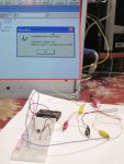
Just getting started with the Picaxe and am getting a 'Hardware not found' error. I'm using a AXE027 USB cable. I installed the driver and the Programming Editor shows it as 'Ready to Use' on the Serial Port tab. I'm on a PC running 64 bit Vista Service Pack 2.

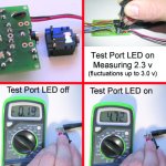
When using Programming Editor's 'Test Port' option the voltage is not steady but floats from -.2 to .3 Volts without the LED lit and with the LED lit the voltage holds a steady 2.30 Volts. (Measured across the Serial In and 0V pins.)

I've tried the Hard-Reset by disconnecting power, hitting 'Program', and then reconnecting power as the program tries to connect to the hardware. Still won't work.

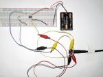
To check my connections: I checked for continuity for the Serial Out and Ground Connections between the top of the micro-chip legs and the appropriate bare metal on the top of the download socket. And I measured 22kohms from the top of the Serial In leg (2) and the download socket (and from the 'Serial In' connection on top of the download socket to the ground measures 9.8 kohms. Also, I'm using 3 AA alkaline batteries for power and my multimeter reads 4.67 volts across the +V and 0V legs on the 8M2.

I built the circuit with another 8M2 chip and all different components on a breadboard and got the same results.

So, I'm stumped. Any help is greatly appreciated.

Thanks,
Scott

Picaxe Help.jpg
 
Last edited by a moderator:

MPep

Senior Member
Welcome to the forum.

By the sounds of it, you may not be using the correct COM port.
You may need to look in the Control Panel, hardware to see what COM port numbers are allocated.
Sorry, I don't have WinVista so can't be any more specific.

USB Com Ports get enumerated to a different COm number in each physical USB port.
 

Nativecorn

New Member
Hi,
Thanks for your response. I selected the COM Port (4) that was listed as 'Ready to Use' on the 'Serial Port' Tab of the 'Options' pop-up. And the 'Scan for USB Cable' test confirms I should be ready to go. And on checking the device manager it confirms the AXE027 as being on COM4. The error message is "Hardware not found on COM 4:" Is there a specific port # I should be using?
 

Grogster

Senior Member
Just out of interest, can you talk to another type of chip using the same setup? Such as an 08M(the earlier version)?

Looking at your attached photo, everything looks OK - perhaps you have a crook stereo socket - they can be a problem, which is why I prefer pin-headers and plugs(a personal choice...)

If you are using the programming lead I think you are, which is the one with the USB-Serial module encapsulated in the USB plug, with a 3.5mm stereo plug on the end of the cord, then there is no easy way to check for continuity, so grab one of those 3.5mm-3.5mm plug-to-plug leads for connecting MP3 players to car stereo's, and plug one end into the proto board, and check for electrical connection on all three points at the other end of the lead and the actual PCB.

Also, what version of the PE are you running?
You need the latest one for the new M2 series chips...
 
Last edited:

Nativecorn

New Member
I'm new to PICAXE so no I don't have another type of chip. (However I have programmed STAMPS via USB from this computer).

Okay, I attached a 3.5mm-3.5mm cord and had successful continuity checks between the cord end and the chip legs for the ground (tip) and the serial out (sleeve). I also measured 22kohms between the cord end (ring) and the top of the serial in leg.

I just tried a new 08M2 as well with no luck.

by the way, I have nothing else on the proto board. In my picture the wires going off to the side are just jumper wires for future use on a breadboard. If I, once I, get this working.

Using 5.4.3 version of PE.

Thanks,
Scott
 
Last edited:

inglewoodpete

Senior Member
I have found the 3.5mm plug connector quite reliable, so I would not recommend changing the connector type at this stage.

My next step would be to test the output of the AXE027 lead at the 3.5mm plug. Using the naming "Tip", "Ring" and "Sleeve", can you check the voltages between 0v (Tip) and Serial In (Ring) when using the PE's "Test Port" tool, without the plug inserted into your proto-board?
 

Nativecorn

New Member
Okay, measured the voltages straight off the AXE027 cable while using the 'Test Port' tool.

Between the tip and ring I get 0 volts with the LED off and with the LED on I also get 0 volts. Not what I expected.

So just for thoroughness I measured the voltages between the tip and the sleeve and got 0 volts both with the LED on and off. I also measured the voltage between the Ring and Sleeve and measured -.19 volts with the LED off and 4.72 with the LED on. (Black probe on the sleeve, red on the ring.)

While I'm being thorough about things I should mention that I'm calling the 'tip' the pointy end of the plug, the 'ring' the center portion, and the sleeve the largest section closest to the cable itself. I mention this cause I feel like I could be missing something really basic!
 

Grogster

Senior Member
Hmmmmm - Curious. At this stage, I am suspect of your USB cable, especially after using the Test Port tool. I don't suppose you have another cable?(...i guess not - that is Murphy's Law...)
 

inglewoodpete

Senior Member
From what you're saying, it seems to me that the tip (yes, the pointy bit at the very end of the cable) and the sleeve (closest to the plastic plug body) connections are reversed. I guess it's not impossible but surprising, since the sleeve would normally be connected the the screen wire of the cable. Maybe the error is actually at the USB-plug end of the cable?

Ideally, you should send it back but I'd be cutting the 3.5mm plug off and soldering another one on correctly (and quietly fuming away to myself!).

Perhaps a second opinion, anyone? Have I got my wires crossed (!) too?
 

Nativecorn

New Member
No, no other AXE027 cable. I assume I should have gotten a voltage reading of around 5.0 volts across the ground (tip) and serial in (ring) with the 'test port' LED on??? Did I get a bad cable?

Just used some leads to swap the 'tip' and 'sleeve'. Still no hardware recognition.
 

Grogster

Senior Member
I agree with that - this is what it looks like - not very likely, but I guess there can always be factory duds... :(

As per inglewoodpete's comment, I would be chopping off the plug and re-soldering as he suggests.

You can work out which wire is which from the plug you chop off, then you can swap them and solder to the new plug.

I will watch this thread to see how you get on.
 

Grogster

Senior Member
Just used some leads to swap the 'tip' and 'sleeve'. Still no hardware recognition.
I'm now stumped too. :(

Anyone else got any ideas?

If it were me at this point, I would be trying to talk to the chip with the same version of PE, on a laptop with an older 9-pin serial port on it and Windoze XP. Perhaps Vista does not like the USB cable for some reason - anyone else here using Vista and the USB cable and no problems?
 

Grogster

Senior Member
Just used some leads to swap the 'tip' and 'sleeve'. Still no hardware recognition.
I'm stumped then. :(

If it were me, I would now be trying the same board and chip, but on an older PC with standard 9-pin serial port and cable.
Perhaps Vista does not like the USB cable for some reason. I have had issues with Vista on more then one occasion...

I don't suppose you have a bog-standard serial-port on another computer or laptop somewhere where you can test that idea?
 

inglewoodpete

Senior Member
I assume I should have gotten a voltage reading of around 5.0 volts across the ground (tip) and serial in (ring) with the 'test port' LED on??? Did I get a bad cable?

Just used some leads to swap the 'tip' and 'sleeve'. Still no hardware recognition.
5v, give or take a bit. You MUST use all 3 wires when attempting to program a PICAXE, since the chip must respond to the "Break" signal (+5v) via the serial out wire.

If you decide to go down the chop-and-replace path, cut the cable a centimetre or 2 from the 3.5mm plug, so that you can strip back the insulation and identify which wire went to which contact on the 3.5mm plug.
 

bfgstew

Senior Member
I am new to Picaxe too, but had a similar problem with my set up. I thought it was the cable at first but traced it to the port it plugs into. Looking at your pics, it does seem fine but double check ALL the tips are properly soldered, also add a capacitor after the power leads, a small 100uF one will do. After I had done that all was fine.
Hope this helps.
Stewart
 

Nativecorn

New Member
Just double checked myself on swapping the leads and nope, doesn't work. I'll have to try another computer (my brothers got a mac) and if that doesn't work I think I'll have to assume the cable's off. Grogster, Inglewoodpete, thanks for all your help, I owe you a beer! I'll post my results as soon as I get onto another computer and test things. And I'll look forward to hearing about anyone's experience using Vista.

Thanks,
Scott

Stewart, just used a 3.5-3.5 cable to check continuity from a cable end to my solder points. All good. Added the 100uf cap but still no luck. Perhaps it's Vista, perhaps a bad cable. Not sure what else it could be at this point. Thanks!
 
Last edited:

Goeytex

Senior Member
A simple way to test the cable is too do a loop back test . Jumper RX and TX together using a paper clip on the phono plug. Then open the PE and then the terminal. Whatever is typed in the lower terminal window should be echoed into the upper window.

This will confirm correct operation of the AXE027 circuitry and the driver. However it will still work if the only problem is that the shield and ring connections are reversed.
 

Attachments

Last edited:

Grogster

Senior Member
Excellent idea, Goeytex. :) I should have said that myself.

The loopback test won't identify if the ring and sleeve are interchanged though.
Assume they are - the loopback test will still work...
 

westaust55

Moderator
I concur with IWP's analysis.

See the diagram in PICAXE manual 1 (V7.7) on page 43 for the allocation of signals.
  • tip = Ground
  • ring = Serial In (voltage should change here wrt the tip when doing the PE "LED" test)
  • sleeve= Serial Out (return signal form the PICAXE to PC)
 

westaust55

Moderator
@nativecorn,

Once you have the problem with the programming side rectified, as a possible suggestion based on what I have done for one of the AXE021 PCB's

I cut away the prototyping area and soldered a strip of header pins to the underside and header socket to the upper side - see attached photo.
Plus a 100 uF 25 Volt electrolytic capacitor in the available holes near where the battery lead would terminate.

Also need to solder two wires to the underside to complete the power traces again as they loop around the rear of the proto area as follows:
1. Positive side of Electro to physical pin1 of the 8-pin socket.
2. Ground side of Electro to ground side of the 10 kOhm resistor (ie end closest the IC socket)

With the above arrangement, I can just plug the remaining board directly into a breadboard spanning 9 consecutive BB holes.
 

Attachments

Last edited:

wllshaw

Member
I typically don't post responses because I am not that knowledgeable, but I have had your same problem when I started. After testing everything, tearing everything down, doing it over, cussing for 8 hrs I couldn't get the chip to download. I finally went back and downloaded the Axe027 driver again. I am not sure if they have two drivers in that download or one, but it worked for me. I have had this same problem once again when I hooked up different computer. I downloaded the axe027 driver once and it didn't work. Without doing anything I just redid the download and it worked perfect. I hope this helps.

Will
 

eclectic

Moderator
I typically don't post responses because I am not that knowledgeable, but I have had your same problem when I started. After testing everything, tearing everything down, doing it over, cussing for 8 hrs I couldn't get the chip to download. I finally went back and downloaded the Axe027 driver again. I am not sure if they have two drivers in that download or one, but it worked for me. I have had this same problem once again when I hooked up different computer. I downloaded the axe027 driver once and it didn't work. Without doing anything I just redid the download and it worked perfect. I hope this helps.

Will
Worth a go.

See
http://www.picaxe.com/docs/axe027.pdf

Page 3, step 6


e
 

Nativecorn

New Member
Hi All, thanks for all your help. I sat down this morning and uninstalled and reinstalled the AXE027 drivers several times. (The preinstall driver never works so I used the zipped files.) I was still not able to program or check the firmware of the 08M2 but on opening the terminal I got the 'Hello, I am your PICAXE 08M2' message repeating time and time again. (I had to choose baud rate 4800 to see it in English.) But I'm still getting a hardware not found error when I try to program in the following program:

main: high 4
pause 1000
low 4
pause 1000
goto main

I even tried a hard reset by hitting program and then re-connecting the battery pack when the status dialogue popped up.

I tried shorting the sleeve and ring as Goeytex suggested and was able to use the terminal to mirror what I typed. So it appears the AXE027 is okay, my power supply and soldering job is okay. I feel like I've gotten somewhere but I'm also more stumped than before.
 

hippy

Technical Support
Staff member
I was still not able to program or check the firmware of the 08M2 but on opening the terminal I got the 'Hello, I am your PICAXE 08M2' message repeating time and time again.

I tried shorting the sleeve and ring as Goeytex suggested and was able to use the terminal to mirror what I typed. So it appears the AXE027 is okay, my power supply and soldering job is okay. I feel like I've gotten somewhere but I'm also more stumped than before.
The cable is okay, the PICAXE serial out to PC connection is okay which just leaves the PC to PICAXE serial in as the possible culprit. Being able to measure 22K from the serial pin and the plugged-in jack lead extension suggests there's a connection straight to the PICAXE and that's also okay.

With Programming Editor Terminal open and it showing "I'm your 08M2" message, use a wire to connect PICAXE leg 1 (+V) to PICAXE leg 2 ( Serial In ) ... does it stop sending the message, put up 'gibberish' ?
 

Goeytex

Senior Member
Seeing the "hello" indicates that the serial out connection is ok and that the signals are not reversed. We know from the loop back test that the AXE027 is ok. Therefore the problem is likely with the serial in signal to the Picaxe.

Looking at your posted images it looks like a solder joint may have been missed.

Suggest you crank up the soldering iron and go over all the joints again, especially those related to the stereo jack and resistors.
 

Attachments

hippy

Technical Support
Staff member
Hi Hippy, Yes, I start getting gibberish on connecting legs 1 and 2.
That's good "everything is working", just that it doesn't ;-)

Disconnect the power and unplug the download cable, and double check that you are reading 22K between leg 2 and the stereo jack pin again.

If not it's perhaps the PICAXE leg not making full contact with the socket.

If it is it could be a voltage issue so double check the Serial Port test, measuring voltage on jack socket and leg 2 of the PICAXE, and check the voltage on leg 1.

I'd first suggest trying Hard Reset again; wait until the pop-up shows "Connecting to hardware..." before turning the PICAXE on.
 

Nativecorn

New Member
I checked my solder points. Those 'unsoldered' points are just the plastic legs on the bottom of the download socket. Made me double check though!

Still getting 22k between the ring of a 3.5-3.5 cable and the top of leg 2 on the chip.

Voltages:
Between 0V and +V: 4.65 volts
During Serial Port Test between legs 0V (8) and Serial in (2):
LED off: a constant fluctuation running between -0.3 and 0.2
LED on: 2.29 volts with jumps to 2.8 volts every 2 seconds or so.
 

MartinM57

Moderator
Those 'unsoldered' points are just the plastic legs on the bottom of the download socket
Doesn't look like it to me - for avoidance of any doubt, you need 5 good solder joints on the socket - i.e. EVERY pin

Compared with the amount of solder everywhere else on the board :))), you've got hardly any on the socket pins
 

hippy

Technical Support
Staff member
LED on: 2.29 volts with jumps to 2.8 volts every 2 seconds or so.
That does sound like a solder short on serial in, something holding the pin halfway between 0V and 5V. Is that at the serial in leg ? What's the voltage at the jack, the otehr side of the 22K ?
 

bfgstew

Senior Member
Seeing the "hello" indicates that the serial out connection is ok and that the signals are not reversed. We know from the loop back test that the AXE027 is ok. Therefore the problem is likely with the serial in signal to the Picaxe.

Looking at your posted images it looks like a solder joint may have been missed.

Suggest you crank up the soldering iron and go over all the joints again, especially those related to the stereo jack and resistors.
Another point, the 2 front pairs of pins on the download socket need to be connected, there maybe a damaged link between them so dab a solder joint between them to make sure.

Good luck.

Stewart
 

Nativecorn

New Member
Okay, I bridged the solder between the two pairs on the 3.5mm socket as suggested. I also went over all my solder points with my soldering gun and made sure they were secure and not connected mistakenly to any nearby points.

And to eliminate WinVista as the culprit I dragged an old PC out of the attic and after a couple hours got it back up and running with Win XP. Download the AXE027 drivers successfully, installed the Programming Editor and ran into the exact same problem.

Then I took some pictures. I took a pic of an identical socket next to my proto board. I'm assuming those five plastic pegs on the underside are for added stability.

Hippy, I wasn't exactly sure what you meant so I photographed what I did. The measurement between the ground leg and the tiny bit of exposed metal on the top of the 3.5mm socket resulted in about 2.3V (with jumps to 3.0v) just as measuring off legs 2 and 8.

And for my own sanity I photographed the voltage results between the ring and the sleeve of the AXE027 when using the 'Test Port' tool. I also tested tip to ring and tip to sleeve and neither of those combinations resulted in in any voltage reading LED on or off.

I put another 08M2 chip in the socket and it said "Hello" but I could not check the firmware nor could I upload the LED blink program. I think I'm going to take up knitting.


PAhelp2.jpg
 
Last edited:

MartinM57

Moderator
Hmmm. Got a breadboard that you can put your spare socket into (extend the pins with wire), 2x resistors and an 08M?
 

flyingnunrt

Senior Member
Whilst you've got that old PC out it could be worth trying the old serial port set up
(instead of the USB) and see if that works.
 

Grogster

Senior Member
I would just like to congratulate you, Nativecorn, at this point - MANY others would have been put off by this, and rather then adopt a process of fault-finding, would just slag-off the PICAXE on the forums, which does no-one any good, and makes no friends.

So, good on you for your perserverence! :thumbsup:

Now, back on track, one more thing I would suggest is that with the old computer with XP you put together, I would NOT be using the 27 USB cable, I would be trying to talk to the chip using the bog-standard 9-pin serial cable arrangement. The wireing for this can be found in the manual in the first few pages, and you still use the same 22k and 10k resistors on the serial programming pins of the chip.

Between all of us here and yourself, we will figure it out!!! :D

Although, I have to admit to having become something of an observer myself at this point...
 

Nativecorn

New Member
You must have been reading my mind! I hooked up a breadboard with the minimum circuit (and a new 08M2, I bought 12). The circuit looks like a bit of a monster but it says 'Hello' in the terminal. However I still cannot check the firmware or download a program on my WinVista machine. And the voltage reading on the 'Test Port' utility reads the same (-.18v LED off and 2.3v LED on).

I hooked up my older WinXP machine and got the exact same results with this breadboarded version of the circuit. Am I wrong in thinking that this almost certainly eliminates every possibility other than a bad cable or a bad batch of chips?

Okay, going to see about the serial cable. Not sure what I have lying around...

PAhelp3.jpg
 
Last edited:

Grogster

Senior Member
You will need a 9-pin "D" line-socket(holes in it, not pins).

If you have a spare 3.5mm headphone or cable, you can chop that and solder the 9-pin to the other end - or just make up a complete cable(which is what I would do) using a D socket and 3.5mm stereo plug...
 

Nativecorn

New Member
OR... instead of sockets and making up a cable I could just use some wires and heat shrink tubing over the appropriate serial connection pins. I don't have a heat gun so a creme brulee torch will do without too too much charring of my computer! (I watched a lot of MacGyver as a kid.)

Success! Thanks to everyone who stuck with me! Grogster, I was losing my mind and a bit of patience but you're right, no point in freaking out in a forum.

So I do still have a problem. I'm not sure how long this XP machine will keep running for me so I'd prefer the USB option on my WinVista machine. Do I simply have a bad cable I should return to PICAXE?

Thanks Again,
Scott

PAhelp4.jpg
 

hippy

Technical Support
Staff member
With the download cable unplugged from the jack measure the voltage between tip (0V) and ring (serial to PICAXE) while doing the serial port test.
 
Top