Generator controller code -

rq3

Senior Member
Merry Christmas, all. This is only my second Picaxe project. The first was very satisfying, and I'm trying to play Apollo era NASA engineer on this one to strip the code as severely as possible. I would appreciate tremendously any and all comments on this code. My intent is for it to run as fast as possible, and I have tried subroutines, select case, and multiple "Starts". This seems to be the best I can do. I know, I know, it's simple and primitive, but the fun
is in the effort (and the fabrication of the board, and the testing, and...).

I've attempted to incorporate previous suggestions as to editing, indenting, use of symbols, etc. Fire at will, or at me if Will is not available.
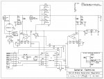
Schematic:
Gen_Reg.jpg


Code:
#rem
*******************************************************
* Code for a Delco-Remy Type A generator regulator. The PICAXE 14M2   *
* does a 10 bit A/D conversion of the generator voltage at Pin C.0,        *
* and a 10 bit A/D conversion of the battery voltage at Pin B.5.             *
* After voltage division by 5.72, op-amps are used to provide a non-      *
* inverting gain of 9.53 and offset such that the A/D inputs are 0-5       *
* volts over a battery voltage of 12.8 VDC to 15.8 VDC. A nominal         *
* 14.3 VDC battery charge (V_Set)results in an A/D conversion output   *
* word value of 512, programmable at 3mV per bit. Battery voltage        *
* under the setpoint causes the PICAXE to turn on the generator field.   *
* Generator voltage higher than the battery voltage causes the PICAXE  *
* to turn on paralleled P channel reverse biased MOSFETS, which act as  *
* reverse current relays. Under-voltage and over-voltage conditions       *
* detected by the PICAXE illuminate appropriate LEDs, and excessive      *
* voltage drop across the P channel MOSFETs is used to flag a high        *
* current condition from the generator and turn off its field.                  *
*******************************************************
#endrem

#PICAXE14M2                                 ;initialize for 14M2
setfreq m32                                    ;set clock to 32 MHz
symbol V_Set=512                           ;charge voltage at +14.3VDC
symbol Bat=w0
symbol Gen=w1
symbol Cur=w2
let Cur=w1-w0

Main:    
                                
    readadc10 B.5,Bat                       ;read the battery voltage
    readadc10 C.0,Gen                      ;read the generator voltage
    
            if Bat<V_Set then high B.1    ;if bat<setpoint, turn on field
                else low B.1
                    endif
                    
            if Gen>Bat then high B.2       ;if gen>bat,turn on P-Ch MOSFETs 
                else low B.2
                    endif
                            
            if Bat<10 then high C.1         ;if bat<12.8 volt, 
                low C.2                          ;turn on LED D5 (undervoltage)
                low C.1
                    endif
                    
            if Bat>1000 then low C.1       ;if bat>15.8 volt
                low B.1                           ;turn off field
                high C.2                         ;turn on LED D4 (overvoltage)
                high C.1
                    endif
                    
            if Cur>20 then low B.1           ;turn off field if current is excessive
                endif
                
goto Main
 

Attachments

graynomad

Senior Member
Well done for indenting, that's rare here :)

Block starts and ends should be on the same column, a more normal way to do an if block is like this

Code:
if Bat < V_Set then 
     high B.1    ;if bat < setpoint, turn on field
else 
     low B.1
endif
I confess though that I'm not up on Picaxe syntax, maybe the code after the "then" and "else" has to be on the same line. If so forget my example.

Also I think using white space around operators make things clearer.
 

lewisg

Senior Member
Interesting project.

I have fiddled with Delco generators before and considered them fairly simple devices. My understanding is that if the key is on and the system voltage was below a setpoint the field would be connected to ground so it would become magnetized and the armature would produce current. Likewise if the system voltage exceeded a setpoint the field would be disconnected from ground. As I recall the tricky part was disconnecting the armature from the battery whenever the car slowed or stopped to prevent reverse current flow. Unlike a automotive alternator a generator is self-exciting so battery condition is not as big a problem.

However all of this is many years and brain cells ago...

As a result I can't evaluate your circuit diagram or code for fitness to this application except to make a few observations:

1. I don't think fast code execution is needed or desired. At the speed the PICAXE would be running you could be switching outputs at a very fast rate. This is to charge a battery. Checking 10 seconds or so would likely be more than sufficient. Running at 4MHz and a pause at the bottom of the code would slow things down.

2. Can you really tell the difference between battery and generator voltage?

3. Here is your code more like I would have done it:
Code:
#PICAXE14M2                  'initialize for 14M2

'constants
symbol V_Set  = 512          'charge voltage serpoint  14.3V =  512
symbol V_Low  = 10           'low voltage setpoint     12.8V =   10
symbol V_High = 1000         'high voltage setpoint    15.8V = 1000
symbol C_Max  = 20           'maximum current setpoint ??.?A =   20

'variables
symbol wBat   = w0           'battery voltage
symbol wGen   = w1           'generator voltage
symbol wCur   = w2           'current (wGen-wBat)

'inputs
symbol BatV   = B.5          'battery ADC
symbol GenV   = C.0          'generator ADC

'outputs
symbol Fld    = B.1          'set high to turn on generator field
symbol Arm    = B.2          'set high to connect armature to battery
symbol Lvolt  = C.1          'low voltage warning LED D5
symbol Hvolt  = C.2          'high voltage warinig LED D4


Do

  readadc10 BatV, wBat
  readadc10 GenV, wGen

  if wBat < V_Set then
    high Fld
  else
    low Fld
  endif

  if wGen > wBat then
    high Arm
  else
    low Arm
  endif

  wCur = wGen - wBat
  if wCur > C_Max then
    low Fld
  endif

  if wBat > V_High or wBat < V_Low then
    if wBat > V_High then
      low Fld
      high Hvolt
      low Lvolt
    end if
    if wBat < V_Low then
      high Lvolt
      low Hvolt
    end if
  else
    low Hvolt
    low Lvolt
  endif
  
  pause 10000

Loop
There may be a few things crossed up but I think you can get the idea of symbols and how they can make your code more readable and keep you out of trouble. Unless I'm completely wet I don't think your over and under voltage code blocks will work as you think they will.
 
Last edited:

rq3

Senior Member
Many thanks, Lewisg. Being very new to this programming stuff, the "nested" if, then routine had escaped me.
Your review of generator/regulator technology is spot on. You may recall that this was (and still is)
done with solenoid driven contacts. The reverse current function you mention is dealt with in my
design with reverse biased P-Channel MOSFETs.

Watching an antique vibrating contact regulator actually function is fascinating. It basically pulse width modulates
the generator field, and both the PWM frequency and duty cycle are automatically set by the regulator as a function
of magnetic field strength feedback to the solenoids from the generator output. When the battery load is low, the
contacts cycle slowly. At high loads, the contacts cycle at up to 300 times per second. How they survive is a miracle,
but I've seen regulators over 50 years old still functioning very well.

My under and overvoltage code blocks seem to simulate well. Unlike your code, they result in a blinking LED (which is OK),
and a pulsed field control signal, which is more in line with the way the old regulators worked. In a fault condition, they would
keep trying at a reduced duty cycle.
 

lewisg

Senior Member
Glad to be of help.

Remember the simulator runs MUCH slower than a running PICAXE.

In operation at 32MHz I doubt you would see the LED on C.1 flicker in this code block:
Code:
if Bat<10 then
  high C.1
  low C.2
  low C.1
endif
YMMV
 
Top