sorry about the jumble last night - westaus - i should know better
First some background:
I have a group of students proto typing retro fitting emergancy lights that could be used in houses, schools officers etc. They would like to use colour and movement as the indicator for the project. The person taking the electrical engineers post started by building and programing a SEB with the classic traffic lights program, from there she investigated a number of options - 1) have a whole series of single colour LEDs and using multiple picaxes, program in a chase fashion similar to the
chase clock produced a number of years ago (my students are still mesmerised by it today) then expand to using shift registers etc to get a whole lot working. 2) investigate using various colours to aid a persons exit from the room - RGB LEDs, we have some RGB LEDs in the lab and a copy of the very simple PWM example given in a silicon chip circuit notebook september 05, this is then interfaced with the
RGB LED Strip from spark fun. this is nice but all 30 rgb leds are the sam colour. The student enjoyed the processes learning how and playing around with the PWM and then the tranistor circuit to control the 12V RGB LED Strip but while looking for the RG LED Strip they came accroos the
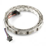 RGB LED Strip - 32 LED/m Addressable - 1m
. A youtube clip of the strip using the
sorce code from the sparkfun website in an adrunio is
here.
The main problem:
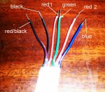
the addressable RGB LED strip uses the
WS2801 IC as the controller for each RGB LED. This IC requires 24 bits of data - 8 bits for each colour giving a grey scale number from 0 to 255 - not on to full on - it then uses PWM to pulse the corresponding colour to get the oppropriate brightness - this is the same process the students were doing with the individual RGB LED and the 08m.
it uses a 2 wire system similar to the others but not the same. you set the clock high - send in a bit - set the clock low and repeat. The second file below is the timing required it is from page 12 of the dtat sheet. from the data sheet it says: " To control the strip, you clock in data continually. Each IC automatically passes the data onto the next IC. Once you pause for more than 500us, each IC 'posts' or begins to output the color data you just clocked in. So, clock in (24bits * 32LEDs = ) 768 bits, then pause for 500us. Then repeat if you wish to display something new."
My problem is - i haven't had any experience with shift register type devices (use i2c regularly and spi once). below is the code i tried last night, knowing that it wasn't completely correct. i was able to talk to the first IC and it moved the data through the 24 bits to give an interesting display. I am currently using a 18m2 but have access to 28x1 and I think an x2? The main problem i see is that the commands are not going fast enough and the IC is premitully posting to the LEDs, give nice effects but not doing what I want it to do.
Code:
'Display various brightnesses of red on the RGB Strip
#picaxe 18m2

let dirsB = 255 ; set all portB pins as output

symbol dataout = b.4		'Define port for data stream
symbol clk = b.3			'Define port for clock


symbol bitcounter = b1		'Define variable names
symbol outbit = b2
symbol outbyte = b3
symbol red = b4

red = 0

Main:

	    gosub shift595		'
		red = red + 1
	    pause 500

	 goto main


'Subroutine to convert a digit to segment codes and shift them into a 74xx595,
' the digit to be sent is in 'counter'

shift595:
	outbyte = red

	for bitcounter = 0 to 7		'Count to 8
	  outbit = outbyte & 1		'Isolate the bit to be sent
	  low clk
	  if outbit = 1 then		'Test the bit, if it's a 1 then
	    high dataout			'set the data out port high
	    else				'otherwise
	    low dataout			'set the data out port low.
	  endif
	 high clk
 	  outbyte = outbyte / 2		'Shift right to position the next bit for output
	next bitcounter
	return
I ubderstand the that code above is only sending 8bits of data and not the required 24bits.
Been reading the manuals, looking at the spiout (shift out) commands and the bit bang version for other parts, still getting my head around these.
Now for my questions:
1) i can access the first 32 bits with the bitxx command, without doing 24 if statements in a row with the clocking wrap around them, can you increment them for a loop function? (every thing is doing it in bytes)
2) what is the time lage of the above, next week when school is back i will get out the cro and look at the traces - 500us is not much time.
3) do i give up and go with the working and ge the kids to scroll through the C++ confusion (for entry level students) that is ardunio?
could use the shift brite that I have - they use good old i2c.
Will continue to post more info as i get it, it is getting late again and I need my sleep - big wiggles concert tomorrow - the young one is excited
thanks
tiny