PcAx anothermarc
Member
I hope you may give me advice on the following subject:
----------------------------------------------------------------
REPLACING PICAXE PROGRAMMER CABLE ?
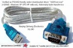
I tried to replace the PICAXE 027 USB/serial cable
with the TTL-232R-PCB module by "ftdichip"
for
a project that needs a permanent "not-too-long-wire"connection
to my circuit.
It did not work -
the pcb was recognised by PICAXE's macaxepad
but
it displayed "strange" letters & it would not program
(message: "xxxxxxx is not connected/could not be found"
or similar when hitting the "program" button)
Different *settings (baude rates etc.) did not have*
any impact on the result.
May you please give me any advice on ...
- what how i should proceed/what i did wrong ?
- what other/similar TTL/232 Module i should use to replace the programming cable ?
----------------------------------------------------------------
MY TRIES
(please see http://imageshack.us/photo/my-images/571/01tries.jpg/)
version 1
TTL-232R-PCB to picaxe chip (08m2)
RXD ----- serial out (pin # 7)
TXD ----- serial in (pin # 2)
on TTL-232R-PCB:
CTS# ---- RTS
... because the PICAXE PROGRAMMER Cable
has the same connection (pls see circuit as listed below)
version 2
TTL-232R-PCB to picaxe chip (08m2)
RXD ----- serial out (pin # 7)
TXD ----- serial in (pin # 2)
----------------------------------------------------------------
RESULTS
(please see http://imageshack.us/photo/my-images/845/02results.jpg/)
though TTL-232R-PCB was recognised
(a check within mac's terminal window confirmed
that it was accepted as usb device)
i did receive strange messages
within macaxepad's terminal window
with a "blank" 08M2 chip
(the default message is smthng like "hello this is your xxx chip")
i tried different baude rates, the result was the same
----------------------------------------------------------------
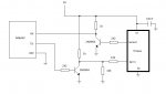
CIRCUITS
circuit PICAXE PROGRAMMER CABLE
http://www.picaxe.com/docs/AXE027.pdf
page 16
circuit TTL-232R-PCB
http://www.ftdichip.com/Support/Documents/DataSheets/Cables/DS_TTL-232R_PCB.pdf
page 12
----------------------------------------------------------------
REPLACING PICAXE PROGRAMMER CABLE ?
I tried to replace the PICAXE 027 USB/serial cable
with the TTL-232R-PCB module by "ftdichip"
for
a project that needs a permanent "not-too-long-wire"connection
to my circuit.
It did not work -
the pcb was recognised by PICAXE's macaxepad
but
it displayed "strange" letters & it would not program
(message: "xxxxxxx is not connected/could not be found"
or similar when hitting the "program" button)
Different *settings (baude rates etc.) did not have*
any impact on the result.
May you please give me any advice on ...
- what how i should proceed/what i did wrong ?
- what other/similar TTL/232 Module i should use to replace the programming cable ?
----------------------------------------------------------------
MY TRIES
(please see http://imageshack.us/photo/my-images/571/01tries.jpg/)
version 1
TTL-232R-PCB to picaxe chip (08m2)
RXD ----- serial out (pin # 7)
TXD ----- serial in (pin # 2)
on TTL-232R-PCB:
CTS# ---- RTS
... because the PICAXE PROGRAMMER Cable
has the same connection (pls see circuit as listed below)
version 2
TTL-232R-PCB to picaxe chip (08m2)
RXD ----- serial out (pin # 7)
TXD ----- serial in (pin # 2)
----------------------------------------------------------------
RESULTS
(please see http://imageshack.us/photo/my-images/845/02results.jpg/)
though TTL-232R-PCB was recognised
(a check within mac's terminal window confirmed
that it was accepted as usb device)
i did receive strange messages
within macaxepad's terminal window
with a "blank" 08M2 chip
(the default message is smthng like "hello this is your xxx chip")
i tried different baude rates, the result was the same
----------------------------------------------------------------
CIRCUITS
circuit PICAXE PROGRAMMER CABLE
http://www.picaxe.com/docs/AXE027.pdf
page 16
circuit TTL-232R-PCB
http://www.ftdichip.com/Support/Documents/DataSheets/Cables/DS_TTL-232R_PCB.pdf
page 12