40x2 acting weird or is it me?

Hi, looking for help
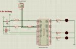
I'm having output issues with my 40x2, and have built a basic board to test it
the only pins i can get to work consistently are B0 to B7
most of the C & D pins won't work

Am I doing something wrong ??

I HAVE USED THIS CODE TO TEST:

let dirsb = %10000000
let dirsc = %10000000
let dirsd = %10000000

main:
high b.7
pause 300
low b.7
pause 1000
high d.7
pause 300
low d.7
pause 1000
high c.7
pause 300
low c.7
pause 1000
goto main

ONLY B7 works !!!

IF I USE THIS CODE:

let dirsb = %11111111
let dirsc = %11111111
let dirsd = %11111111

main1:
let pinsB = %11111111
pause 1000
let pinsB = %00000000
pause 1000
let pinsc = %11111111
pause 1000
let pinsc = %00000000
pause 1000
let pinsD = %11111111
pause 1000
let pinsd = %00000000
pause 1000
goto main1

the B pins flash on and off rapidly !!!!

Other weird things sometimes happen as well
eg
if i turn it off and unplug the serial cable and then turn it back on again it won't work at all!
I have to turn it off and plug the cable back in !!!


Is the chip faulty or is it me!
cheers
Paul
 

westaust55

Moderator
Your program code looks okay and simulates corretly.

Is this the first time you have used the 40X2?

Can you post your schematic diagram of your board and if possible a good clear photo of the circuit.

How are you checking the outputs?
If you are using LED's what value of series resistor are you using for each LED to limit the current?

Keep in mind that there are various current limits for PIC/PICAXE chips.
For the newer 40X2 (PIC18F45K22) these limits are:
20 mA for an individual pin is usual guide (25mA absolute Max)
xx mA for an entire 8-pin port - not stated in datasheet
185 mA absolute Max as total sourced from all ports if PIC junction temp < +85 degC
70 mA absolute Max as total sourced from all ports if PIC junction temp > +85C and < 125 degC

Maximum current out of VSS pin (-40°C to +85°C).................................. 300 mA
Maximum current out of VSS pin (+85°C to +125°C)............................... 125 mA
Maximum current into VDD pin (-40°C to +85°C) ................................... 200 mA
Maximum current into VDD pin (+85°C to +125°C) ................................ 85 mA
 
Last edited:

Haku

Senior Member
A picture of the board and/or schematic will probably help stop us trying to guess wether you've got both ground pins connected to ground & both +V pins connected to +V, a capacitor across the power pins, a pullup resistor on the reset pin, etc. etc.


edit: westaust, I think I'm seeing double, problems with the new board?
 
Last edited:
Hi yes
Yes i is the first time with the 40x2
I'll check all the current limits on the pins
and I'll check the circuit again
unfortunately no camera available

cheers
 

westaust55

Moderator
edit: westaust, I think I'm seeing double, problems with the new board?
Yes - your not having eye problems :cool:
I have had a few times in the last couple of days where I get double posts.
Sometimes a post seems to hang and then the posts goes "through" maybe after 5 minutes
Have deleted the duplicate post
 
Hi
Thanks for you time
Tried to upload an VSM image but couldn't get it to work!!
I've double checked everything
using 330R resistors for leds
All seems OK
but still needs the USB download cable plugged in in order to run
weird
Is it possible that 3 AA batteries are not sufficient?
cheers
Paul
 

westaust55

Moderator
Hi
Thanks for you time
Tried to upload an VSM image but couldn't get it to work!!
Try doing a screen capture to a "Paint" program and save as a jpeg file to upload.

I've double checked everything
using 330R resistors for leds
All seems OK
:
Is it possible that 3 AA batteries are not sufficient?
With 4.5V supply and if 2V forward voltdrop across LED's then that equates to roughly 8 mA per IO pin
8 pins per port x 8 mA = 64 mA so should be okay.

Are the batteries new/fresh and really supplying 1.5 Volts each under load?

but still needs the USB download cable plugged in in order to run
Often a sign of a poor supply (voltage in general or dropping under load) and grounding - all 0V points conencted together correctly including the 10 kOhm resistor on the Serian In pin.
 
Last edited:
Try doing a screen capture to a "Paint" program and save as a jpeg file to upload.

With 4.5V supply and if 2V forward voltdrop across LED's then that equates to roughly 8 mA per IO pin
8 pins per port x 8 mA = 64 mA so should be okay.

Are the batteries new/fresh and really supplying 1.5 Volts each under load?

Often a sign of a poor supply (voltage in general or dropping under load) and grounding - all 0V points conencted together correctly including the 10 kOhm resistor on the Serian In pin.
Hi

I did try a screen grab but the uploader limited me to an image of ~640x280 at a max of ~19K
the image was so poor I didn't bother.

Yes batteries are new

I solved the problem of it not running without being connected to the cable
bad solder connection on the RXD 10K resistor to GND........ oops!

I'm only testing the IO pins 21 to 40
of these
B0 to B7 are OK
C2, C3 and C4 are also OK
C5 to C7 and D4 to D7 don't work

Since I'm lost here I'm going to order a new chip and compare the 2

Thanks for all you input
Much appreciated
 

hippy

Technical Support
Staff member
Your electrolytic capacitor is also shown inverted; the filled rectangle should connect to 0V, the empty rectangle should connect to +V.
 

westaust55

Moderator
View attachment 9079

Excellent it worked this time
this time a JPG instead of a PNG

cheers
Using a jpeg type file was first suggested. At least you have learnt how to upload a file.

You stated by only posting some program code, but as per initial guesses the request for the schematic or photos was founded as hardware is proving to be the root cause.

If there is a lesson here, it is to ensure that sufficient details are provided from the start.
 
Top