which antenna for 433 MHZ transmitter/receiver?

srnet

Senior Member
http://www.hoperf.com/rf_fsk/fsk/

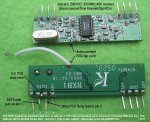
"A high precision local oscillator (LO) is generated by an integrated VCO and △∑ Fractional-N PLL synthesizer. The
synthesizer is designed to support configurable data rates, output frequency, frequency deviation, and Gaussian
filtering at any frequency between 240–960 MHz"

The modules do advertise having frequency hopping capability, so should in theory be capable of changing frequency fairly quickly.
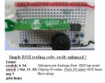
 

John West

Senior Member
This is getting pretty far afield from the subject of Cold Fusion Reactors, ;) so I'll stop with this post and get back with you later if I have some time to delve into it further.

As best as I understand it, the sigma/delta fractional N PLL setup uses more than one cyclical divider count value, (it changes the divider count value back and forth on the fly in order to synthesize small frequency steps,) and that creates what I'd describe as "locking noise" (I don't know the correct terminology) in the VCO as it's adapting to the new count.

The fix for this noise comes in the form of programmable filters, the proper characteristics of which depend on all of the variables in the system, from the reference freq to the operating freq, to the bandwidth required and the frequency hopping rate (if that's a requirement.) It's more a matter of redesigning the entire phase-locked loop in software for each new frequency desired than it is a matter of simply picking out a new number to plug into the counter/divider. Thus the reason for the spreadsheet, so I can see why you thought it a difficult task for a PICAXE to do on the fly. It is.
 

srnet

Senior Member
This is getting pretty far afield from the subject of Cold Fusion Reactors
Sure is, but then that thread is not about cold fusion either.

You can set up a frequency hopping start frequency and channel spacing, then alter a single register to hop to another channel.

Problem here is the channel size is 10KHz, but typical 434Mhz channel spacing is 25Khz as I recall.

I will try it sometime, seeing how fast the frequency can be changed by altering the 3 main carrier registers ($75,$76,$77).
 

manuka

Senior Member
Given the musing we should perhaps start this FSM quest as a fresh topic.

It struck me that the popular SpiritOn/Keymark Rx module (sold Aust./NZ by Jaycar) could suit such a simple FSM project,as it has a PICAXEable RSSI tap. Many 433 MHz field trials end up as solo affairs of course,since buddies who may help at the "wave your hand if you can still hear me" level soon tire of the tweaking. Hence it's well worth having a 2 way link that'll locally inform about how the far end is seeing your TX & antenna adjustments. Just suitably pulsing a local LED (or a piezo changing tones) may be enough for insights?

Check the undocumented hack below- there are further details at +> www.picaxe.orcon.net.nz/433RX.htm
PICAXE treatment of this weak RSSI feed (~2-3 Volts but at just a few mA) is easy enough.
 

Attachments

srnet

Senior Member
I mentioned this as I went through a similar exersise when evaluating antennas for a 2.4Ghz Video downlink for my Aerial Photography. There are a great many antennas available very cheap for this frequency as in WiFi antennas. I dont own a 2.4Ghz field strength meter .......

I modified a Video RX to give external access to the AGC line (via a buffer of course) and was able to test various antennas by recording the AGC volts at various distances from the transmitter.

I did develop a program (for a PIC) that turned the AGC volts into a tone, this was very useful for pointing a directional antenna (patch or small yagi) for best signal. However for antenna comparative measurements you would also need a digital output, this can be as simple as a digital multimeter.

For field measurments of antennas, I used a multimeter that has both analogue indication (remember when multimeters had pointers ?) and a digital output. The analogue indicator allowed easy orientation of the RX antenna for max signal whilst the digital output gave an easy to read figure.
 

boriz

Senior Member
"I did develop a program (for a PIC) that turned the AGC volts into a tone, this was very useful for pointing a directional antenna (patch or small yagi) for best signal."

Cunning. Like it.
 

manuka

Senior Member
Aside from mere technicalities, the technique used may relate to human perception of course. We're pretty snappy when it comes to judging standalone tonal or flicker rate variations, but not so good on loudness & brighness changes (unless continually compared to a standard). Hang glider pilots, & even model plane fliers, have long used a tone variation acoutic variometer to quickly indicate soaring or sinking altitude changes.
 

srnet

Senior Member
I am making some headway on working through the problem with the RFM42.

It appears to be induced RF causein the chips POR to activate, nut current spikes caused by the varryin current load (from 1ma to 80ma in a few mS).

I built a dummy load for the antenna, bit of co-ax terminated in a 47R resistor and the resistor put in a tim with the lid shut at 100mW it did not need filling with oil .......

With this setup its has yet to go into POR, 30,000 tranmissions and counting.

Need to go to the sweetie shop to see which are still in smal 'real' tins, Altoids I know of, or maybe a small snuff tin.
 
Top