ADC pin protection from overvoltage

vshortt

Senior Member
Hi All,

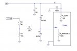
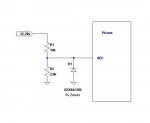
I'm building a circuit that needs to be able to detect whether the incoming voltage is 12-14v or 24-28v DC. The detection is the easy part. Use a voltage divider and send the result to an ADC pin. Easy.

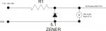
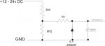
The part I'm concerned about is overvoltage. If for some reason more than about 28v gets sent down the line I need to be able to protect the ADC pin from getting blown. My thought is to use a zener 5.1v diode.

The schematic below provides an output voltage of around 5v at the voltage divider when a 24v source is applied. (about 2.2v when a 12 volt source is applied). So how do I size my zener and what size R1 do I need? I'm confused. I'm thinking that I need a 1 watt 5.1 Zener and a 45ohm 1 watt resistor at R1. Does this sound correct? Seems like I would be dissipating (wasting) a lot of energy through the resistor so these numbers don't sound right.

Keep in mind all I'm doing to sending a voltage to an ADC pin for reference.

I know this is probably basic electronics 101, but being a hobbyist, you learn what you need when you need it - and I've never needed this before. Any circuit I've ever used that had a zener in it was made by someone else. I just put it together. So sorry for such a basic question and thanks for any replies in advance!

new-2.JPG
 

jtcurneal

Senior Member
I don't see what value resistors that you are using for your voltage divider circuit.
Without those values, it is impossible to know the current involved and therefore the value of R1 in your circuit.

or even know if you need another resistor

Joel
 

jtcurneal

Senior Member
I am wondering about the values of your resistors.
Maybe that 8R2 resistor should be 8K2

Zener diodes require a minimum current to work correctly, I would probably try 4k7 and 1k resistors, that will give you about 5 ma passing through the zener when your supply is about 28 volts without needing the R1 resistor shown in your diagram. a 400 - 500 mw zener should be all you need (.004 amp x 5 volts = .02 watts dissipation )

Joel
 

vshortt

Senior Member
First: yes, it's 8k2 - sorry.

I see what you mean. with the 1K and 4K7 resistors, I'm calculating a little over 23v out of the divider, allowing the zener to supply 5.1v. BUT: what happens when I'm only supply 12 volts? I'm still getting almost 10V through the divider, meaning the zener will still supply 5.1v, right? That would mean no detecting the different voltages. I need to be able to detect 12v,detect 24v and protect from over-voltage all at the same time.

With the resistors in my divider now, I'm getting 5v out at 24v in (if I remember right) and 2.2v with 12v in. leaving the two resistors as they are, how will the zener react when it's supplied with less than it's rated voltage? will it all get dropped accross it, or will it allow UP TO 5.1v to pass, dropping anything above that?
 

MFB

Senior Member
The zener approach to overload protection can introduce significant errors. I would recommend using a rail-rail I/O opamp in the non-inverting unity gain configuration and protecting this with a (say,100K) resistor in series with the non-inverting input. This should clamp the signal to the ADC input to within a few tens of mV of each supply rail.
 

Goeytex

Senior Member
Consider the attached Diagram.

12v in = 2.0v at ADC Zener Does nothing
24v in = 4.0v at ADC Zener Does nothing
30v in = 4.7v At ADC Zener does nothing
40v in = 5.0v at ADC Clamped by Zener

Zener current is limited by R1 and The resistance of
the Zener itself. It will be approx 1 ma.

Total power dissipated by the Zener is about 5mw

The zener does not dissipate any significant heat
Therefor can be sized at 1/8 or 1/4 watt. (Smaller if you can find one)

However R1 will dissipate about 130 mw @ 40V

Note:
The voltage divider was sized so that the Zener has zero effect on ADC through
the operating range of 0 - 28v where 0 v to 28v in = 0 to 4v at ADC. So the Picaxe is
does not even need protection until the input voltage reaches about 30v.
 

Attachments

Last edited:

jtcurneal

Senior Member
I could be wrong, but my tests have shown that when your voltage in is less than about 25 volts the Zener will not conduct.
As if the Zener was not even there.
above about 25 volts, the zener starts conducting.
at 12 volts in, the output should be about 2.1 volts. at 24 volts the output should be about 4.2 volts, above 26 volts the output should be no more than 5.1 volts. depending on the exact values of the components used.

Joel
 

vshortt

Senior Member
Thank Joel, thats great!

Thats what I was looking for. I don't think it will ever see over 30v, but better safe than sorry.

Cheers!

V
 

womai

Senior Member
The standard way of protecting the input is a diode between ADC input and VCC (supply voltage, in your case 5V) - pointing towards VCC -, and a second diode from GND to the ADC input - pointing towards the ADC input. This protects the circuit against both positive overvoltage and negative voltages (limits excursion to one diode drop above VCC and one diode drop below GND). A limiting resistor of suitable size limits the maximum current that needs to be dissipated (should never be much more than ~1mA). Your voltage divider already acts as such.

Use fast Schottky diodes which switch quickly in case of overvoltage and have smaller voltage drop (~0.3V) than "normal" Silicon diodes (~0.7V), hence clamp the voltage closer to the supply rails. E.g. BAT85 is a good choice. Actually this scheme is what the Picaxe has internally for ESD (electrostatic discharge) protection, but the internal diodes aren't really designed to carry that load for very long (they can't dissipate much static power). I.e. you do need to add your own diodes external to the Picaxe. Also the standard Picaxe download circuit makes use of these internal diodes - the 22 kOhm resistor limits the current to a safe value. Fast Schottky diodes are faster and cheaper than Zener diodes.
 
Last edited:

fernando_g

Senior Member
As womai mentions, use schotkys instead.
If you are willing to consider SMT devices, the BAT54S has two diodes specifically connected that way, in a single SOT23 package, which is not difficult at all to solder.
 

womai

Senior Member
Actually you want a BAT54SFILM, not a BAT54AFILM. Anode (left pin) goes to GND, Cathode (right pin) goes to VCC, center pin goes to ADC input.
 

Dippy

Moderator
I agree with womai. For overvoltage suitable series resistance (whether in a pot-div or simple series) plus this method of clamping is the best way for an economy job.

Zeners will affect the signal as they approach the zenering voltage.
You could have a higher val zener somewhere else for belt&braces transients if you want.
For a slow ADC circuit like this I'd also have a small ceramic from ADC pin (to ground).

With standard clamping ensure you have adequate precuations (high enough sereis res) so that the clamping current isn't too high esp if you have a weedy voltage supply. If you affect the supply voltage you will affect the ADC value. Once you get the design balance right then you'll be fine.

I did some tests a while back with over-voltage transients and using fast external diodes versus the standard internal PIC ones. I found the internal ones were pretty slow. Choice of clamping diode device, whether a fancy smd package or a couple of fast discrete schottkys is up to you.

But I certainly wouldn't use a 5V zener when the signal might approach anywhere near that. It will behave like a voltage controlled resistor with a bad tempco so in conjunction with those other resistors you will get slightly unpredicatable IR drops. Pain in neck IMHO, especially when a proper solution is easy.


This has cropped up numerous times before with same answer , maybe someone could write a blog or nice little tutorial...
 

MartinM57

Moderator
I agree with womai...I woke up in the middle of the night and realised that but didn't think the current Mrs MartinM57 would have appreciated me firing up the laptop and correcting myself ;)
 

MFB

Senior Member
One effect often overlooked when using diodes for protection is that, although they prevent damage, an overload on one analog channel can introduce errors on other in-range channels.
 

Goeytex

Senior Member
Attached is a schematic diagram captured from LTSpice of the circuit described by womai.
When run in a simulation the transient analysis shows excellent response to overvoltage
transients. The only thing I am not sure about is the ideal value for R3.

I say this because so many here recommend higher currents for ADC inputs and suggest
no more higher than a 10K pot when inputting to and ADC. Honestly I have not found that
to be necessary in my prototypes where a 100K pot works perfectly well. But granted that
I have an ultra stable supply and proper decoupling on all IC's.

As far as the Zener approach goes, I would not demonize it off hand. If the divider
is designed so that the zener does not come into play until past the input working range,
it will have zero effect upon the ADC operation. For example in this circuit where 0 - 28 volts
in to the divider produces 0 - 4 volts out..... The input to the Picaxe does not even need
protection unless the supply reaches over about 32 volts. A 5.2V zener will have no effect
over the 0- 4 volt range. The application here is to simply detect whether the voltage is
12 v or 24 v. So even if there were a small error introduced by the Zener ( there won't be)
it is irrelevant to this application. We are not measuring something where a perfectly linear
10bit resolution is needed.

Sometimes "Good Enough" is good enough.
 

Attachments

Last edited:

Dippy

Moderator
Blimey Martin ... you were THAT worried about a slight slip that you lost sleep?
I know people are often paranoid about making a mistake on the Forum , but oh dear..... I'll phone Jeremy Kyle as you need treatment from 'the team' :rolleyes:

Absolutely Goey; horses for courses, but it's nice to introduce people to the basics of design and, at least, introduce the concept of good design. Personally, if it got to design nitty-gritty I'd breadboard it anyway. The value of R3 depends , in the Real World, on PIC type and ADC speed. I assume PICaxe uses the 'general purpose' slow RC for ADC conversion? For general purpose use I'd say that was trifle high. Personally I'd increase the pot div absolute values to keep power down and decrease R3 to 1K. Check diode spec. We're in danger of all agreeing :)
 
Last edited:

womai

Senior Member
The only thing I am not sure about is the ideal value for R3.
Microchip typically recommends 10 kOhm source impedance maximum. That said, if you use a pot then the two partial resistances (R_a = wiper to upper pin, and R_b = wiper to lower pin) effectively act in parallel as far as source impedance is concerned, i.e.

1/R_source = 1/R_a + 1/R_b

where of course

R_a + R_b = R_pot is the total resistance of the potentiometer. The worst case (highest effective source impedance) is with the wiper at the center, i.e.

R_a = R_b = R_pot/2

where R_source = R_pot/4. So in order to fulfilll the 10 kOhm requirement you can actually use a pot with up to 40 kOhm and be fine. Of course the Microchip recommendation has some margin built in, which explains why Goeytex can get away with a 100 kOhm pot.
 

fernando_g

Senior Member
Martin;
I've also awaken in the middle of the night because I've had nightmares of electrolytic caps chasing me. Specifically 1000 uf @ 25V from United Chemi-con.
 
Top