Spark Fun IMU Fusion board

centerice1919

New Member
Hi,

I am using a 28x2, via i2c, to try and read from the first register of the imu board. My code is:

main:
hi2csetup i2cmaster, 0x68, i2cfast, i2cbyte
pause 100;
readi2c 0, (b0)
pause 500;
debug

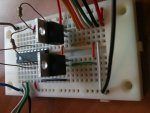
I have the 28x2 at 3.6v, 4.7k pull up resistors, I have also tried using line level converters using MOSFETS and have the same problem. I was able to communicate over i2c using a different device with both circuit configurations. I don't understand why I cannot read the register.

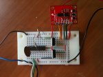
link to the imu board:
http://www.sparkfun.com/products/10252

Thanks in advance
 

lanternfish

Senior Member
The 28X2 defaults to an 8MHz internal clock speed. Your code should read:

Code:
main:
hi2csetup i2cmaster, 0x68, [B]i2cfast_8[/B], i2cbyte
pause 100;
readi2c 0, (b0)
pause 500;
debug
Pg 76 of PICAXE Manual 2 explains this.

Cheers
 

pete20r2

Senior Member
second that,

HI2CSETUP I2CMASTER, slaveaddress, mode, addresslen

Mode is the keyword i2cfast (400kHz) or i2cslow (100kHz). Note that these keywords must change to i2cfast_8, i2cslow_8 at 8MHz, etc.
pg 74 of the second part of the picaxe manual
 

centerice1919

New Member
Hi,

Thank you for the i2cfast_8 that keeps me from getting $FF when reading. I'm still having a problem communicating with the I2c device. The device communicates at 3.3 +/- .5v and i have tried directly connecting the device to the 28x2 at 3.6 volts and i have also tried using MOSFETS and have the 28x2 at 4.6 volts and the i2c device at 3.3 volts. When i read from any address it always return $69. If the i2c device is connect directly, or through the MOSFETS or not connected at all the 28x2 outputs $69, no matter which resister i try to read to. Any suggestions?

Code:
main:
	hi2csetup i2cmaster, %01101000, i2cfast_8, i2cbyte
	pause 500;
	readi2c 12, (b0)
	pause 500;
	debug
	let b0 = 0
	goto main
[\code]

Thanks
 

pete20r2

Senior Member
Can you clarrify what voltage your logic is running at.
0 - 3.3v logic may not be enough to register a true on 0 - 5v logic.
 

rob nash

Senior Member
hi
am still learning ,but looking over the data sheet u already have the 4.7K on the ADXL345 board so u dont need them next to your picaxe.

as for the program try

"hi2csetup i2cmaster, 0x68, i2cslow, i2cword"


good night
rob
 

hippy

Technical Support
Staff member
When i read from any address it always return $69 ...

hi2csetup i2cmaster, %01101000, i2cfast_8, i2cbyte
The $69 is the same as the I2C Device Address with the R/W LSB set. This is usually symptomatic of an I2C Bus error, possibly wrong or missing pull-ups or crossed-over SDA and SCL.
 

pete20r2

Senior Member
Do you mean, can I run the one I have at 3.3v?
If you have the 5v version, run it no lower then 4.5v for reliable operation.
There is a 3.3v version available though.
 

centerice1919

New Member
Hello everyone,

Yesterday i asked a friend of mine who has an arduino uno if i could try and connect my imu fusion board to that and test it. He let me and it work perfectly using the code found here:
http://www.hobbytronics.co.uk/arduino-adxl345-imu3000

I connected the fusion board directly and also through my mosfet circuit to the arduino. The circuit I used is described here:
http://www.hobbytronics.co.uk/mosfet-voltage-level-converter
Except I only used 4.7k resistors and the resistors on the 3.3v side are included in the IMU fusion board.

I have two of the fusion boards and I have verified that both are functional. I decided to switch to the 28x2 to a18m2 picaxe (its more ideal for my application). I have the line-level converter in place but am receiving only $ff when reading.

This is my basic code for trying to read just a single register:
Code:
init: 
	setfreq m32
	goto main
	
main:
	i2cslave $68, i2cfast_32, i2cbyte
	pause 3200
	readi2c $00, (b1)
	pause 3200
	debug ' I only am debugging and hope to serout in the future
	'serout c.3, n2400, (#b1)
goto main
I have tried i2cfast_32, slow_32, i2cword, and i2cbyte in every possible combination

I decided to mirror my code to the best of my knowledge off of the arduino code that work and this is what i came up with.

Code:
symbol gyro = 0x68
symbol reg_gyro_x = 0x1D
symbol accel = 0x53
symbol accel_power = 0x2D
setfreq m32;
setup:
	hi2csetup i2cmaster, gyro, i2cfast_32, i2cbyte
	'Sample Rate 1kHz, Filter Bandwidth 42Hz, Gyro Range 500 d/s 
	hi2cout 0x16, (0x0B);       
    	hi2cout 0x18, (0x32);
    	hi2cout 0x14, (accel);     
	hi2cout 0x3D, (0x08);
	hi2csetup i2cmaster, accel, i2cfast_32, i2cbyte
	hi2cout accel_power, (8);     
    	hi2csetup i2cmaster, gyro, i2cfast_32, i2cbyte
    	hi2cout 0x3D, (0x28)
	goto main
	
main:
	hi2cin reg_gyro_x, (b21,b20,b23,b22,b25,b24,b15,b14,b17,b16,b19,b18)
	debug b1
	pause 1000;
	goto main
I also have set the 28x2 in i2c slave and the 18m2 in i2c master and had them communicating across i2cfast to each other. So, i know the i2c works on both chips.

I attached picture of my breadboard.

I feel as though i'm missing some magical link that the arduino code makes that i don't see or understand. I'm pretty confident that i need to use i2cfast and i2cbyte according to the imu-3000 datasheet.

Thanks for your help!
 

Attachments

centerice1919

New Member
I forgot, regarding the pictures:
The blue line is ground
The brown line is 5v+
The black line is ground
The red line is 3.3v+.

Thanks again!
 

centerice1919

New Member
Thank you!!! hippy that was the problem. I can now read from the gyro with no problem!

I have two questions:
(1) how does $68 translate into $D0 and why?
(2) the gyro is capable of reading the attached accelerometer, I have configured the gyro to allow for i2c pass through so i can enable the accelerometer. I am having trouble writing to and reading from the accelerometer. Do i have to do a similar conversion from the address $53 to $?? ? The accelerometer is a ADXL 345.

Thank you
 

hippy

Technical Support
Staff member
Yes, it's a similar issue for the ADXL354, from -

http://www.hobbytronics.co.uk/datasheets/ADXL345.pdf

"7-bit I2C address for the device is 0x1D, followed by the R/W bit. This translates to 0x3A for a write and 0x3B for a read. An alternate I2C address of 0x53 (followed by the R/W bit) can be chosen by grounding the SDO/ALT ADDRESS pin (Pin 12). This translates to 0xA6 for a write and 0xA7 for a read".

That would be $A6 in the HI2CSETUP.

I2C Addresses are usually 7-bit ( there's also 10-bit ) and there are two ways to represent such addresses; as 7-bit, or 8-bit with a R/W lsb added ( which is usually set to zero ). The PICAXE uses the 8-bit format. You need to read the datasheet, determine if it's given as 7-bit or 8-bit ( either described or shown in a timing diagram ) and then translate if necessary to the PICAXE 8-bit representation.
 

centerice1919

New Member
Awesome, now it makes sense. Thank you sooooo much! I am now reading the accelerometer data as well.

Here is my final working coded for anyone in the future having similar problems

Code:
symbol gyro = $D0
symbol reg_gyro_x = $1D
symbol accel = $A6
symbol accel_power = $2D
setfreq m32
setup:
	pause 3200;
	
	hi2csetup i2cmaster, gyro, i2cfast_32, i2cbyte
	'Sample Rate 1kHz, Filter Bandwidth 42Hz, Gyro Range 500 d/s 
	hi2cout 22, ($0B);
	pause 3200
	hi2cin $16, (b0)
		       
        'set accel register data address
    	hi2cout 24, ($32);
    	pause 3200
    	hi2cin $18, (b1)
    	
        'set accel i2c slave address
    	hi2cout 20, ($53);     
	pause 3200
	hi2cin $14, (b2)
	
        'Set passthrough mode to Accel so we can turn it on
	hi2cout 61, ($08);
	pause 3200
	hi2cin $3D, (b3)
	
        ' Reset slave address to accel
	hi2csetup i2cmaster, accel, i2cfast_32, i2cbyte
	'set accel power control to 'measure'
        hi2cout accel_power, ($08)     
    	pause 3200
    	hi2cin accel_power, (b4)

        ' Return Slave address to gyro
    	hi2csetup i2cmaster, gyro, i2cfast_32, i2cbyte
   
        'cancel pass through to accel, gyro will now read accel for us
    	hi2cout $3D, ($28)
    	pause 3200
    	hi2cin $3D, (b5)
    	
        debug
    	pause 32000
	goto main
	
main: 
        'Read Gyro Registers'
	hi2cin 0x1D, (b21,b20,b23,b22,b25,b24,b15,b14,b17,b16,b19,b18)
	'display accel and gyro values
        debug b1
	pause 1000;
	goto main
Thanks again everyone for their HELP!
 

centerice1919

New Member
One more question.

If i want to read i2c and have multiple tasks how would i accomplish that? Do i have to adjust the I2CFAST_32 to something else? I would like to use up to 4 tasks but the number running at anyone time from 1-4.

Thanks

nevermind i retract this comment it seems to work fine with _8 (my guess is 32/4 = 8 haha)
 
Last edited:
Top