Reading 24 bit data

SAborn

Senior Member
I have reached a limit on figuring out how to read 24 bit data into 3 registers and would like some help and a example block of code to how this is done.

The chip used clocks the data in msb first, and each bit is clocked in via a sclk pin.

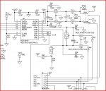
The data sheet for the chip used is attached.

Perhaps i have just run out of brain cells, but i have hit a brick wall on this one.

Picaxe chip is a 08m
SCLK is on pin 2
Data is on pin1

Little miffed here.
Thanks in advance
 

Attachments

lanternfish

Senior Member
Have you tried using the spiin command (pg 218 Manual 2)?

And by polling the data pin for its data ready state. Active low when data is ready.
 

SAborn

Senior Member
No i have not as yet, but how do i use the command for 24 bits of date as what i read it works for 16 bits.

Would you care to give an example for 24 bit data.
 

hippy

Technical Support
Staff member
It looks to be a simple SPI bus; send out 24 pulses and read the data either just before the pulse goes low again or just after ( you may need to experiment ). For an X2 you can have quite simple code using the 'bptr' variable, untested ...

Code:
Symbol DIN_PIN = pin2
Symbol CLK = 1

Low CLK
bPtr = 2
For bitCount = 0 To 23
  PulsOut CLK, 1
  @bPtr = @bPtr << 1 | DIN_PIN
  If bitCount = 7 Or bitCount = 15 Then
    bPtr = bPtr - 1
  End If
Next
That will put the 24-bits in 'b2:b1:b0' or 'bit23..bit0'.

Alternatively, which should work for the 08M, you can read each 8-bit byte at a time ...

Code:
Symbol DIN_PIN = pin2
Symbol CLK = 1

Low CLK
For bitCount = 0 To 7
  PulsOut CLK, 1
  b2 = b2 * 2 | DIN_PIN
Next
For bitCount = 0 To 7
  PulsOut CLK, 1
  b1= b1 * 2 | DIN_PIN
Next
For bitCount = 0 To 7
  PulsOut CLK, 1
  b0 = b0 * 2 | DIN_PIN
Next
If reading after the pulse falling edge does not work, then replace ...

PulsOut CLK, 1
b0 = b0 * 2 | DIN_PIN

with ...

High CLK
b0 = b0 * 2 | DIN_PIN
Low CLK
 
Last edited:

Dippy

Moderator
Just a comment or two in passing as I have to mow the lawn....

SPIin allows several variables. 3 bytes = 24 bits.

Or, if that doesn't work, can you do a manual bit-bang into 3 byte variables?
It's usually just a matter of a clock-pulse , read the pin state, store, shift and repeat. Sometimes it's ; set clock pin high, read state, clock pin low , store, shift, repeat.
I haven't read the Data Sheet for that device (a sin I know) so I don't know if there are any timing issues, but I've done a lot of banging with PICs (or 'raw' PICs as you call them here). And it's worked a treat.

...and I hope you will pay great care with application design with such a pretty ADC :)

Right, where's my grass box gone?
 

SAborn

Senior Member
Thanks guys,

Im still having some issues with the data but will try again tomorrow with a clear head and get back to you with results.

Dippy,
the grass box should be between the mower and the fool chasing it. :D
When you are done you can come and cut my grass if you want.(or i need to buy a sheep) {trouble with that is keeping the Kiwi's out, as they have a fetish for sheep}
 

SAborn

Senior Member
Sorry, a little lost on what ADC you are reffering to.

To my understanding all ADC is done within the chip and 24 bit data of the conversion is the output value.

Have i missed somethink here??
 

Dippy

Moderator
Umm... the link you gave is to the ADS1231 24bit ADC.
I'm referring to that :confused:


Have you ever used >12bit ADCs?

Have you considered the circuit design/layout/references that are required for use to take greatest advantage of this resolution?
And, by that, I mean getting GOOD results as opposed to any old results.

If you haven't then I suggest you do a bit of research.
If you have a crappy design then you are simply wasting bits (and your own time).
 

inglewoodpete

Senior Member
Sorry, a little lost on what ADC you are reffering to.

To my understanding all ADC is done within the chip and 24 bit data of the conversion is the output value.

Have i missed somethink here??
I concur with Dippy. Unless you do some very careful circuit design with a rock steady power supply, at best you could get 14 bits of valid data (I'm more generous than Dippy) and 10-bits worth of noise making up the 24-bit output. (14 bit values can be accurate to 0.006% but that level of sensitivity is affected by changes in humidity, electric and magnetic fields, including mains hum, radio transmission, stray capacitance & inductance etc). To the ordinary experimenter, it is near impossible to go beyond 12 or 14 bits and get any meaningful value.
 

westaust55

Moderator
Have you tried using the spiin command (pg 218 Manual 2)?

And by polling the data pin for its data ready state. Active low when data is ready.
SPIIN command is only in the firmware for the X1 and X2 parts so no go when it is an 08M

Must use bit-bashed code as per hippys example
 

SAborn

Senior Member
Ok, i have some results today.
What a difference a clear head can make, i found i had a circuit fault as i had neglected to connect a link to the digital voltage supply.:confused:

Yes the lower bytes are useless at present due to noise and i did research the adc setup further and found input filtering a must.

Will also revise the voltage regulator circuits as there could be noise there too.

At present it is on a single sided board and will change to a double sided board with a full ground plane, as ground impedance is listed as one of the biggest causes to noise.

Any other recommendations to design to reduce noise that i have missed thus far?

TI gives a schematic for a board they supply and will use this information, should anyone care to look and make any recommendations here is the input side of the circuit.

One question regarding the schematic is R23 and R24, would you read these as 0 ohms or a miss print?
 

Attachments

Last edited:

Dippy

Moderator
Oh, we're going to blame a hangover are we? ;)

It's good that you've searched around.
Now you can see the idea (that I keep banging on about) wrt PCB layout.


0 Ohms or misprint? (Maybe "Miss Print" was behind the bike sheds huh?).
What does the BOM say?

http://focus.ti.com/lit/ug/sbau175/sbau175.pdf
Page 25 , Item No. 26.

You will sometimes find zero-ohm links in ref designs where the designers think some other options may be useful or likely.
 

SAborn

Senior Member
Thanks Dippy for your input and thanks Hippy for your code examples.

Using a modified version of Hippys code example and allowing 5 reads for the load cell to stabilize, then just using the upper 16 bits of data, it gives a very consistant reading that i can calibrate to kg's and tested with calibration weights up to 150 kg with 100% results or down to 1 kg with consistent readings.
A further calibration in code and it will read 100 grams within +/- 10 grams.

This is without any filtering added to the front end as yet, and expect to acheive even better results with a better designed circuit board as Dippy bangs on about ;)

The load cell in use is rated to 300kg so ultra fine low measurements is not expected or even required in this case.

The end use will be for weighing livestock and measurements to the last gram is not required or even practical for this application.

Thanks to all that have taken the time to comment here and have give further food for thought in regards to design.
 

Dippy

Moderator
That's good news. I mean that seriously (for a change;)).

You'll always find that making the final product more stable and smooth and shielded will make a huge difference.

It's usually the case that spending a couple of hours in the design can save hours/days when it's built. Research is always worth it - especially when you are going for accuracy/precision.
There are so many App Notes and Design Tips kicking around it's always a good idea to listen to Manufs etc. as those poor devils have spent hours/weeks developing things just like that Ref design you found.


Anyway, good luck with it.
 

SAborn

Senior Member
Further update.

I had an olds set of supermarket scales here that no longer worked.
They were rated to 20kg, so out of curiosity i unplugged the load cell and wired it into the 24 bit adc chip.

A few lines of code change and suprisingly it reads very accurate even down to almost 1 gram, by placing a AA battery on the scale it will read a consistant 24 grams which is what my cheap kitchen scales say as well.

Placing a 10kg weight on the scale gives a reading of 10,000 grams (funny enough)

And again without using the lower 8 bits, so the mind boggles at how well these converters work if in a stable noise free enviroment and all 24 bits are used.

Looking forward to getting the needed components to complete the new design board and seeing if the lower 8 bits are stable enough for use.

I would highly recommend the ADS-1231-ID chip for use with a load cell even with a less than desired setup as i currently have (purpose built single sided board with no filtering)

I can see the next project will be revamping the old supermarket scales with a Axe and a I2C display.

Now wheres my parts shopping list?
 

botronics

New Member
I'm trying to read a MCP3551 22-bit ADC from Microchip with a 40X2, ver B3 picaxe. With the SPIout command, I just get zeros. A scope shows a set of sclks, but the sdata looks like its trying to output, but the levels are only about a volt and not 5 volts. The result are all zeros at sertxd.

The program:

'20 bit dac Microchip MCP3551

'Symbols
symbol cs = A.5
symbol sclk = A.7
symbol sdata = A.6
symbol mode = 1

startup:

high cs


getbytes:

low cs
pause 100

spiout sclk,sdata,mode,(b1/2,b2,b3)


high cs

sertxd (#b1,",",#b2,",",#b3,13,10)

pause 500

goto getbytes

end

I tried Hippy's code and I got was 254's for both cases. I not sure what is causing the sdata line to remain a choppy low.
 

westaust55

Moderator
@ botsmaker,

Welcome to the PICAXE forum.

A few comments:

1. It would be far better to start a new thread rather than append to the back of a thread from about 1 year ago.

2. When posting program code, if there are more than a few lines (ie about 3) you should put your code within [code] and [/code] tags as described in the sticky post &#8220;Read Me First&#8221; at the top of the Active forum area.

3. For more constructive comments on your program:
(a) you say you are trying to read the ADC chip which seems reasonable since an ADC is usually taking an analog signal and providing a digital value which a microcontroller can read.
(b) your program is using the SPIOUT (SHIFTOUT) command which is used to send data out. I think you need the SPIIN or SHIFTIN command.
(c) the chip is a 22-bit ADC chip, your only comment in the code is: '20 bit dac Microchip MCP3551
. but the SPIOUT command is only trying to &#8220;read&#8221; 18 bits with the SPIOUTsection " (b1/2,b2,b3) " as 2 bits, 8 bits and 8 bits.

Note that the fact that you have been trying to output data from the PICAXE to the Output pin of the ADC chip could have resulted in damage to either or both chips. If one is putting out a high level when the other outputs a low level there is a short and often something fails. So please be aware that there may have been component damage.
I am not 100% sure if the SHIFTOUT command does automatically set the designated pins as outputs (note to self - something to check) . If not, that may have prevented damage in the absence of DIRx command.
 
Last edited:

botronics

New Member
Reading MCP3551 ADC

@ botsmaker,

Welcome to the PICAXE forum.

A few comments:

1. It would be far better to start a new thread rather than append to the back of a thread from about 1 year ago.

2. When posting program code, if there are more than a few lines (ie about 3) you should put your code within [code] and [/code] tags as described in the sticky post “Read Me First” at the top of the Active forum area.

3. For more constructive comments on your program:
(a) you say you are trying to read the ADC chip which seems reasonable since an ADC is usually taking an analog signal and providing a digital value which a microcontroller can read.
(b) your program is using the SPIOUT (SHIFTOUT) command which is used to send data out. I think you need the SPIIN or SHIFTIN command.
(c) the chip is a 22-bit ADC chip, your only comment in the code is: '20 bit dac Microchip MCP3551
. but the SPIOUT command is only trying to “read” 18 bits with the SPIOUTsection " (b1/2,b2,b3) " as 2 bits, 8 bits and 8 bits.

Note that the fact that you have been trying to output data from the PICAXE to the Output pin of the ADC chip could have resulted in damage to either or both chips. If one is putting out a high level when the other outputs a low level there is a short and often something fails. So please be aware that there may have been component damage.
I am not 100% sure if the SHIFTOUT command does automatically set the designated pins as outputs (note to self - something to check) . If not, that may have prevented damage in the absence of DIRx command.
You are right on all points. I should be using the shiftin command. I need an idle high, read after clock, which is only supported with a B.4 version picaxe (mode 6). I have the version b.3. I was able to read all the bits the ADC can offer by writing the program in a very open and machine like fashion. I get confused when writing loops inside of loops. My scope was my friend while the program was running. The final program will require all the bits to come out on optos to be read by a GPIB interface. When I get the vers. B.4, I will try the shiftin command again. At least the ADC is good and is working.
 
Top