Picaxe cutoff circuit ?

curry87

Senior Member
Looking for a circuit that will do the following a picaxe monitors the voltage supplied to it when it drops to a certain level it triggers a switch that will cut the power off to it self and other devices and stay that way until reset.The low voltage cutoff circuit must use under 1ma or better during the cutoff phase so that sensitive voltage sources ain't completely discharged even after a low voltage event has occurred also allowing 200ma of current to pass.
Ideas please ?
 

westaust55

Moderator
How about posting a circuit or at least a block diagram.
Where does the Picaxe currently fit into the circuit?
Is it working with the devices drawing the 200 mA load current?
Which Picaxe already in use?

Can the Picaxe control the load power supply via a transistor?
Some Picaxe have low power sleep mode which others have already posted about. Shut all loads off with Picaxe via transistors and put the Picaxe into low power mode might well get below the sought 1 mA post shutdown current draw
 
Last edited:

Pauldesign

Senior Member
Hey Curry,

There lots of options, so i'll just list possibles components and i believe you can figure out the rest (the setup and basic interfacing) depending on your need; but if u can't you're welcome to shout :eek:

- Op-amp as a comparator
- Use a PICAXE that has latch feature e.g 18M2, 20X2 etc
- Brown reset chip
- Load management switch e.g FPF2116
- Opto-coupler
- Flip-flops or D-Latch
- A large capacitor
 

curry87

Senior Member
Added diagram only concentrating on the picaxe cutoff circuit and nothing else so left that blank the picaxe im using a 18m2 in diptrace they didn't have that model so used 18x to illustrate it instead.

Basically the 18m2 reads an internal voltage reference adc when it detects the voltage dropping below 4v it sends a pulse of any length up to picaxe supply voltage which cuts off all loads including itself until some external reset is applied.

When the low voltage event occurs i need all loads including the picaxe that has triggered the event to be cutoff from the voltage source.
 

Attachments

Last edited:

westaust55

Moderator
Added diagram only concentrating on the picaxe cutoff circuit and nothing else so left that blank the picaxe im using a 18m2 in diptrace they didn't have that model so used 18x to illustrate it instead.
But all the available PICAXE chips are available in the cummulative libraries of mycroft and myself:

At post 3, my DIPTRACE library now includes:

  • PICAXE 18M2
  • PICAXE 20X2
  • PICAXE 28X2
  • PICAXE 40X2
Click on the arrow in the quote at the right of user name to goto the thread :)
 

Svejk

Senior Member
Instead of swithing the high side, consider switching the ground. Connect your picaxe and load to C2, when power is applied, through Reset switch, make C1 high to keep the ground swithced. Make C1 low to cutoff.
 

Attachments

KMoffett

Senior Member
Instead of swithing the high side, consider switching the ground. Connect your picaxe and load to C2, when power is applied, through Reset switch, make C1 high to keep the ground switched. Make C1 low to cutoff.
Be aware that leaving Microchip controller chips hooked to VCC and removing the ground can leave current leakage paths from Vcc through I/O pins to ground. :( Been there, done that!

Ken
 

Dippy

Moderator
I thought there were a couple of suggestions in Paul's reply that were perfectly good.
Curry didn't even acknowledge them....?

A (suitable) MOSFET (or a smart FET type thing) can act wonderfully as a high-sided switch to your whole circuit.
An op-amp , voltage-comparator or a supervisory chip such as a TPS3823 could easily switch the MOSFET.
You set the threshold, and you can design in some hysteresis (which is really needed) and bingo.

The only thing to keep an eye on are the downstream devices and how they behave. Sorry, haven't time to go into detail. Others will.

Curry, if you need help with understanding the electronics just ask.
It really is easy and quite educational too.
If this is for a school project let us know.
 

eclectic

Moderator
Curry87.
I see that you flit on to the Forum,
then flit off again.

Following Dippy,

why don't you at least
acknowledge replies?

People here have spent time to try and help you.

Or are you too busy weighing pies where you are?

e
 

westaust55

Moderator
Curry87.
I see that you flit on to the Forum,
then flit off again.

Following Dippy,

why don't you at least
acknowledge replies?

People here have spent time to try and help you.

Or are you too busy weighing pies where you are?

e
maybe sampled the pies and (V)indaloo
 

curry87

Senior Member
I apologize for not getting back sooner been very busy and no not pie related.Some good solutions to my problem thanks will try them all to find the best one that works in my case.


When the pixace has entered low power mode by using "end" are all outputs left untouched in their original state before the end command low/high ?
 

Pauldesign

Senior Member
Hey Curry,

Acknowledgments are our motivation to assist;)

Basically the 18m2 reads an internal voltage reference adc when it detects the voltage dropping below 4v it sends a pulse of any length up to picaxe supply voltage which cuts off all loads including itself until some external reset is applied.

When the low voltage event occurs i need all loads including the picaxe that has triggered the event to be cutoff from the voltage source.
Just bear in mind, the controlling PICAXE must always have power (alternatively, u should design such that when in sleep mode, it should run from a battery e.g CR2025 button cell) while all the loads connected to it have been switched OFF.

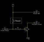
Cutoff design illus:

By using FPF2116; u need just a PSU source; all the loads (Don't exceeds the current and capacitive loading specs) will be connected to the output of the device while only the controlling PICAXE is connected to the input side of FPF2116. Use the Latch feature of your 18M2 to apply a controlling signal to the control pin of FPF2116. A high to the control pin will switch ON power to all the loads while a load will switch OFF power to all the loads after which, u'll have to put 18M2 in sleep mode and when there is a signal to the reset pin, it gets out OFF sleep mode and do what ever u want.

U can't totally cut power OFF the controlling device! otherwise how will it monitor/control the loads connected to it. How will it react to an external reset if there is no power to it! Except you want to do that manually and hence there is no need for the flipping reset because flipping the power switch manually is same as resetting the entire circuit.

When the pixace has entered low power mode by using "end" are all outputs left untouched in their original state before the end command low/high ?
You can figure this out yourself by simulating your codes in PICAXE PE.

i.e write a simple program including output pins and the end command; run the program in manual mode and see what it does (monitor the output pins states when the end command is executed).
 

kevrus

New Member
I would use a latching relay. No current used to maintain an energised state, just the picaxe monitoring circuit, which would then pulse the relay to latch/unlatch.
 
Last edited:
Top