inglewoodpete
Senior Member
Overview
This software, written for the 20x2 PICAXE, is for an Infrared code receiver that runs in the background. It is designed to work with the 32-bit NEC IR format, which is used by most domestic IR remote controls. During testing, the code has performed reliably with a number of different IR remote controls including: Topfield, LG, Grundig and Akai.
Using the edge-triggered hardware interrupts of the 20x2 allows the IR code reception to run in the background, causing minimal interference with the main tasks of the user’s PICAXE code. Once enabled, the receiver software captures and stores the IR code in background processing, setting flags to indicate the status of the IR signal reception. A timer supervises the IR code reception to ensure that incomplete data packets are rejected.
For a description of the NEC IR protocol, refer to my following post.
Hardware and Firmware
The IR Receiver module should be wired in accordance with the circuit described in Manual 2, IrIn command except it is limited to pins that can handle hardware interrupts. In the case of the 20x2, this is B.0 (hInt1) and B.1 (hInt2). The code has been tested on hardware interrupt 2 (B.1). Firmware version C.1 or higher is required.
Features and Limitations
The 20x2 must run at 64MHz to process the incoming IR data. The length of the IR zero bits (1 to 1.2mS) restricts what code can be included in the interrupt routine. An IR status byte can be accessed at any time to determine the status of reception. During code reception, any instructions in the main code that last longer than normal should be avoided (eg serial, shift-in and –out etc). User code can test the tInfraBusy bit to determine whether to run long commands or to wait.
Timer interrupts are available for use but your code must allow for the timer being reset on reception of any IR signal.
The servo command uses timer 1 so is incompatible. Any features that use internal interrupts (refer Manual 2 Appendix 4) may interfere with IR reception.
The ‘repeat’ feature of the NEC IR format is not supported.
Software
The sample code posted here is a working demonstration of background 32-bit IR reception. It simply displays the received IR code in the PE terminal window in binary and hexadecimal. The code should work if simply pasted into the PE and downloaded into a 20x2 connected to an IR receiver module as described.
The IR receiver uses hardware interrupts to determine the elapsed time of each bit. Initially triggered on the falling edge of the header, the reception process commences. At this point, several variables and the timer are initialised, with the major tick set to about 140uS while the timer rollover interrupt is set to 115mS.
The next hardware interrupt occurs on the rising edge of the header, preparing for data reception. The data bits are read on the falling edge of each bit’s IR signal. As each hardware interrupt occurs, a copy of the major tick timer value is taken and the elapsed time, since the last interrupt, is stored in a byte of scratchpad memory. The incoming bit times are stored in the last 34 bytes of the scratchpad memory, the initial 2 bytes for the header part 1 and 2 signature times and the remaining 32 for the 32 bits of data. When the scratchpad pointer rolls over back to zero, 32 bits have been received, the timer is disabled and other IR status bits configured. If 32 bits are not received before the timer rollover interrupt occurs, the whole process is reset and re-enabled for reception again.
The lower part of the scratchpad can be used for other tasks but must be managed to prevent overwriting.
To maintain the short processing times required, 3 word (or 6 byte) variables are reserved exclusively of IR reception. I have selected the highest 3 words for ease of management. A single byte variable within the range b0 to b3 is required to manage the IR status within the interrupt routine. This is poked to RAM when not required and can be accessed from the user code.
I am not a fan of the GoTo command; however it is required in the interrupt routine to reduce handling time of each zero bit. As a principle, interrupt routines should be kept as brief and simple as possible. Believe it or not, for the task, this routine is as simple as possible.
Adapting the code for your own requirements
When used in a normal situation, the receiver would check the device ID and accept or reject the signal. An additional check can be made on the values stored in the first 2 buffer bytes: the header signature values can be compared with expected values, although this is not normally required. For remote codes that support the command integrity check, you can perform an ‘Or’ function on the two command bytes (received Bytes 3 and 4). The result should always be $FF.
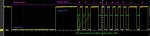
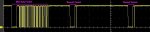
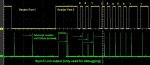
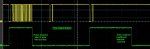
The attached screen shots show the activity on the oSynch and oTimer pins, useful in understanding and debugging the code.
Thanks to hippy for your assistance in configuring the hardware interrupts.
This software, written for the 20x2 PICAXE, is for an Infrared code receiver that runs in the background. It is designed to work with the 32-bit NEC IR format, which is used by most domestic IR remote controls. During testing, the code has performed reliably with a number of different IR remote controls including: Topfield, LG, Grundig and Akai.
Using the edge-triggered hardware interrupts of the 20x2 allows the IR code reception to run in the background, causing minimal interference with the main tasks of the user’s PICAXE code. Once enabled, the receiver software captures and stores the IR code in background processing, setting flags to indicate the status of the IR signal reception. A timer supervises the IR code reception to ensure that incomplete data packets are rejected.
For a description of the NEC IR protocol, refer to my following post.
Hardware and Firmware
The IR Receiver module should be wired in accordance with the circuit described in Manual 2, IrIn command except it is limited to pins that can handle hardware interrupts. In the case of the 20x2, this is B.0 (hInt1) and B.1 (hInt2). The code has been tested on hardware interrupt 2 (B.1). Firmware version C.1 or higher is required.
Features and Limitations
The 20x2 must run at 64MHz to process the incoming IR data. The length of the IR zero bits (1 to 1.2mS) restricts what code can be included in the interrupt routine. An IR status byte can be accessed at any time to determine the status of reception. During code reception, any instructions in the main code that last longer than normal should be avoided (eg serial, shift-in and –out etc). User code can test the tInfraBusy bit to determine whether to run long commands or to wait.
Timer interrupts are available for use but your code must allow for the timer being reset on reception of any IR signal.
The servo command uses timer 1 so is incompatible. Any features that use internal interrupts (refer Manual 2 Appendix 4) may interfere with IR reception.
The ‘repeat’ feature of the NEC IR format is not supported.
Software
The sample code posted here is a working demonstration of background 32-bit IR reception. It simply displays the received IR code in the PE terminal window in binary and hexadecimal. The code should work if simply pasted into the PE and downloaded into a 20x2 connected to an IR receiver module as described.
The IR receiver uses hardware interrupts to determine the elapsed time of each bit. Initially triggered on the falling edge of the header, the reception process commences. At this point, several variables and the timer are initialised, with the major tick set to about 140uS while the timer rollover interrupt is set to 115mS.
The next hardware interrupt occurs on the rising edge of the header, preparing for data reception. The data bits are read on the falling edge of each bit’s IR signal. As each hardware interrupt occurs, a copy of the major tick timer value is taken and the elapsed time, since the last interrupt, is stored in a byte of scratchpad memory. The incoming bit times are stored in the last 34 bytes of the scratchpad memory, the initial 2 bytes for the header part 1 and 2 signature times and the remaining 32 for the 32 bits of data. When the scratchpad pointer rolls over back to zero, 32 bits have been received, the timer is disabled and other IR status bits configured. If 32 bits are not received before the timer rollover interrupt occurs, the whole process is reset and re-enabled for reception again.
The lower part of the scratchpad can be used for other tasks but must be managed to prevent overwriting.
To maintain the short processing times required, 3 word (or 6 byte) variables are reserved exclusively of IR reception. I have selected the highest 3 words for ease of management. A single byte variable within the range b0 to b3 is required to manage the IR status within the interrupt routine. This is poked to RAM when not required and can be accessed from the user code.
I am not a fan of the GoTo command; however it is required in the interrupt routine to reduce handling time of each zero bit. As a principle, interrupt routines should be kept as brief and simple as possible. Believe it or not, for the task, this routine is as simple as possible.
Adapting the code for your own requirements
When used in a normal situation, the receiver would check the device ID and accept or reject the signal. An additional check can be made on the values stored in the first 2 buffer bytes: the header signature values can be compared with expected values, although this is not normally required. For remote codes that support the command integrity check, you can perform an ‘Or’ function on the two command bytes (received Bytes 3 and 4). The result should always be $FF.
The attached screen shots show the activity on the oSynch and oTimer pins, useful in understanding and debugging the code.
Thanks to hippy for your assistance in configuring the hardware interrupts.
Attachments
-
 43.9 KB Views: 320
 -
 55.5 KB Views: 228