PICAXE to measure a 12v Battery

Husos

New Member
Dear All,

I have checked the forums (searching using "12v Battery measure") and didnt come up with what I want.

AIM:

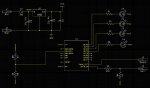
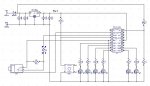
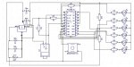
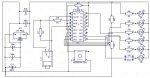
I want to use a picaxe to measure the voltage in a 12v battery and then have LEDS to indicate charge status (not sure how I will split the ratio). By charge status I do not mean when its charging but rather what the current charge is like (i.e. 100%, 80%, 60%, 50%). I might even use a seven segment display (3 of them to show voltage 12.6, 12.4 11 etc)

[a] is this possible
where would i find resources to help me with this one
[c] has anyone done this before

Husos
 

Husos

New Member
further explanation

Thanks for the response it has helped a bit in my search.

I have a 12V battery that I am attaching to a 12V switch and then to my picaxe project, I have already built the Regulator to drop it to 5v using a 7605 to power the picaxe circuit.

from what I understand having read (bear in mind I am an absolute beginner at both picaxe and electronics) the forum is that I take another feed of the 12v battery positive connect this to a 10k and 4.7k (in series) and then connect this to the adc? and then have the 12v Neg also attached to the picaxe negative.

Beanie Bot at the time posted this:
Battery 0v to PICAXE 0v.
Battery positive to one end of 10k.
Other end of 10k to 4k7
Other end of 4k7 to 0v.
Join of 10k & 4k7 to ADC input pin of your choice.

not sure I understand the last two lines. Once some clarifies I will try to create a sechamtic and post here to make sure its right.

12v + -> 10K resistor -> 4k7 Resistor -> ADC0 on picaxe 18x

Husos
 
Last edited:

Chavaquiah

Senior Member
Another keyword you can use for searching is "monitor." Along with "battery" this will give you a few more threads.

As for the voltage divider, think of it as a T shaped:

Code:
12 V  ----  10k  ----- 4k7 ---- 0V
                   |
                   |
                  ADC
The voltage reaching the Picaxe will be 4.7 / (10 + 4.7 ) x 12V = 3.84V (someone please check this! My knowledge in electronics is severely lacking). You'll need to know this value to properly use ADC.
 

fernando_g

Senior Member
A better solution would be to use a 10k and a 5k resistor. That way, you get a nice round 3:1 divider (i.e. for 12v battery = 4v ADC in).
Makes the calculations a lot simpler in the Picaxe's integer-only math.

How do you get a 5k resistor? Simply parallel two 10k ones.

Also, use 1% or better still, 0.1% tolerance resistors. Precision resistors no longer cost an arm and a leg.
 

Husos

New Member
my first schematix

Dear all please look at this schmatic and comment as required, this is my first ever attempt. I used a 5v regulator and it should be a 7805 as is in my breadboard but could not find it. Still have alot to learn about DipTrace. Is there a tool that can tidy up the schematic and arrange a bit more professionally as mine looks to me like spagetti.

How would I put two 10k in parallel so they gave me 5K? Sorry for what is proabably a stupidly simple question.

Husos
 

Attachments

hippy

Technical Support
Staff member
It's always a good idea to draw 0V (ground) lines along the bottom of a circuit, 12V, 5V etc along the top. It's a convention which makes things easier to follow.

Other than the connections for the download socket not going to the right socket pins ( ring is not 0V ) everything else looked okay to me with a cursory glance.

Added : Actually, no - If you follow GND from the PICAXE down, left, up and around it leads to the regulator output. And you've got PICAXE +V connected to 0V.
 
Last edited:

Taniwha

Senior Member
What drawing program do you use?

Dear all please look at this schmatic and comment as required, this is my first ever attempt. I used a 5v regulator and it should be a 7805 as is in my breadboard but could not find it. Still have alot to learn about DipTrace. Is there a tool that can tidy up the schematic and arrange a bit more professionally as mine looks to me like spagetti.

How would I put two 10k in parallel so they gave me 5K? Sorry for what is proabably a stupidly simple question.

Husos
I am curious as to which drawing software you used to make this drawing?

Thanks
Stewart
 

Husos

New Member
Opps

The error in my schematic stems from where the 5 volt reg comes out, they should be reversed, i put the + to the - on the and the - to the + once it leaves the 7805 chip.

Stupid mistake ....doh! otherwise that then fixes it correctly, please see new JPEG

Husos
 

Attachments

Husos

New Member
I am curious as to which drawing software you used to make this drawing?

Thanks
Stewart
First of all I never realised so many of us KIWI's are on this forum (I was born in Hellensville (Auckland) and then moved to Wellington (plimmer Steps)...

Anyways Stewart I used DIPTRACE

Sorry for the update just wanted some feedback on my second attachment

Husos
 
Last edited:

Husos

New Member
Srry to Hassle

Hi Guys,

Sorry to hassle you, just really wanted some feedback on my second attachment.

Husos
 

techElder

Well-known member
A schematic looks so much better and is easier to read if it is laid out with the inputs on the left and the outputs on the right. Not always possible, but a goal to work towards. Yours has some bottom up direction.

Use the the symbols for ground and V+ instead of snaking wires all around your drawing.

In your schematic, you have the LEDs wired in a common anode configuration, but you have them drawn in a common cathode configuration. Need to reverse the leads. That error would have been so much easier to see if you had used the V+ symbol. Instead, I had to trace that long V+ wire around your drawing until I figured out where it came from.

Keep at it! You'll get there.
 

Dippy

Moderator
Patience Husos. Remember, people here are volunteers and doing the work for YOU free of charge!! :)

Firstly, thank you CAD drawing. And practice will make perfect, so I'm going to give you some blunt tips as I won't beat about the bush ...

"How would I put two 10k in parallel so they gave me 5K?"
- just put two 10Ks in parallel... eh... what's the problem ??

"Is there a tool that can tidy up the schematic and arrange a bit more professionally as mine looks to me like spagetti."
- LORDY! do it yourself , it would take 5 minutes of your time with a simple circuit like this.
Get into the habit of good practice and stop relying on 'tools' , which may or may not exist and may or may not even work.;)

PLEASE remember this for the future - people will click-away if they have to spend too much of their unpaid valuable time interpreting....


Firstly, try and keep to a standard where power lines are kept top and bottom.
The section around the regulator is a bit messy.
More messy = harder to check = errors likely to go unnoticed = more likely to be wrong. (Sherlock Holmes 1895)

Some of your wires are close together and makes me cross-eyed following them around (consider using the 'signal' method where you just lable a wire or connection).


1. Regulator.
Capacitors. Are those the types and values specified by the Data Sheet of the EXACT device you are using?
I have seen all sorts of specs depending on the PRECISE type of the generic 7805.
Double check.
2. Jack socket. I can only assume you have got this right.
3. For good ADCing always have a decoupling cap on the PICAXE power pins. It really can make a difference.
4. Your LEDs look wrong way around. If the schematic was tidier you'd have probably noticed this. Sorry to criticise, but it's often true.

5. Consider...
a) using high-bright LEDs and higher value resistors. It can take the strain off things.
b) using a non-dinosaur regulator with low quiescent current.
Both of these can make your battery last longer if this is an issue or requirement.
 

MartinM57

Moderator
10 mins with Diptrace (and about 2 years experience ;)) - it's not the right circuit and I haven't labelled everything properly, but it's very close to yours and a bit simpler :)

The key thing is the use of "Nets" and the ability to connect pins to the Nets without wires...

Also, using a proper schematic symbol for the PICAXE which is logically laid out, rather than representing the physical layout helps the "left to right"ness of the whole thing

EDIT: Top tip is to set the Diptrace background to black (View|Colours menu item) - much easier on the eye...
 

Attachments

Last edited:

Dippy

Moderator
I'm not a Diptrace person and I prefer a white background personally (as its like pen on paper rather than a Victorian chalk on a blackboard :) )

Although I use different CAD, I'd have done it - in principle- exactly as Martin has.

Note: Ranger CAD calls it 'signals' which must be the same as DT 'nets' (as does Easy-PC) -
apologies if that caused confusion.

Note2:
Nets/Signals are an implied connection and helps de-clutter the schematic drawing, whilst maintaining the net connectivity within the design.
 

hippy

Technical Support
Staff member
@ MartinM57 : Nice circuit. On background colour I don't think you'll ever get agreement. I usually prefer white-on-black, but peculiarly for circuits and PDF files get on better with a traditional Windows black-on-white.

Not saying the circuit is wrong ( it's not AFAICT ), but where to connect the 12V being measured is an interesting point. At "Safe12V" that's okay but you are measuring the reservoir capacitor rather than instantaneous 12V. One could connect to before the diode, the actual 12V input, but I'd be tempted to add another diode from the 12V input and run that through the voltage divider. It all depends on exactly what it is one wants to measure, what one wants to achieve.
 

Husos

New Member
Thank you

Hi Guys,

I just wanted to clarify a few things and also say a big thank you for all the help, comments, positive critique and feedback.

I am not looking for anyone to do the work for me as I want to do it myself, like anything in life you have to start somewhere and sometimes you cant see the woods for the trees. I tried for several hours to get my schematic looking good and was pretty proud of my first attempt, especially considering I have never done anything like this before. Having read the comments and seen the version that Martin57 (thank you for this, I never would have figured that out on my own) I realise that I need to put alot more thought into it, make it alot clearer, seperate out differnt bits and overall figure out alot more on my own.

I will be honest and say I am finding this all a little daunting and even stressful (although alot of fun to boot). Its nerve racking when you put your work up for others who have so much experience to crtique especially when you know you you are lacking.

Husos
 

Dippy

Moderator
It'll always be daunting husos.
And it's simply a matter of putting the time in and gaining experience.
For someone as experienced as Martin, that schematic probably took him 10 minutes from scratch.

But, remember, when you get as clever as many here then it's even worse.... why? because if you post something and it has a newbie error people tut-tut a lot and have a good laugh.

Don't worry about it. Just take it on the chin or argue your reasons. We can't see you blush ;)


You haven't said whether you have understood the comments made ... specifically re: LEDs and reg capacitors.....???
That would help us :rolleyes:
 
Last edited:

manie

Senior Member
Husos:
You are BRAVE !!! To post a schematic that is. Two years back when I started I went straight into PCB design and posted THAT ! Well done, keep at it, you will come right.... just don't start posting PCB's as I did (remember Dippy,Hippy et al.......) I have come a long way with this forum.......
 

Dippy

Moderator
Gosh, is it 2 years manie?
Those were the days when that famous equation was dervied:
Manie + MOSFET = Bang! :)
 

John West

Senior Member
10 mins with Diptrace (and about 2 years experience ;)) - it's not the right circuit and I haven't labelled everything properly, but it's very close to yours and a bit simpler :)

The key thing is the use of "Nets" and the ability to connect pins to the Nets without wires...

Also, using a proper schematic symbol for the PICAXE which is logically laid out, rather than representing the physical layout helps the "left to right"ness of the whole thing

EDIT: Top tip is to set the Diptrace background to black (View|Colours menu item) - much easier on the eye...
MartinM57: If it were me - I'd add pin numbers to the chip. But that's just me. I'm old-fashioned. :D
 
Last edited:

Husos

New Member
Attempt number 3

Dear All,

Right here goes attempt number 3. I have read all comments and tried to take everything into account.

Dippy, No I didnt understand what was meant by "LEDs and reg capacitors" ... allthough I have been reading about LEDS and trying to understand. The two 10K in parallel giving 5 also threw me a bit as to how to do this (sorry Newbie statement), I have read up on serial and parallel but just cant see it, nor how to fit it into my diagram

I Intend to use this circuit using a deep cycle 12v Battery and my aim is to measure remaining battery life on the single 12v. Then display LED status (100%, 90%, 80%, 70%, 60%, 50%)

Husos (as alwasy thx for patience)
 

Attachments

hippy

Technical Support
Staff member
Wow. That's far better than I usually manage so you seem to have a natural knack for this, much greater than I have. And an impressive example of taking things on board.
 

Dippy

Moderator
That's really good now. Far better.

The point made about the LEDs was about which way they were pointing.
Remember, they are DIODES and need to point in a particular direction.
In your previous schematic they were wrong. It wasn't clear if it was a simple placement error (which we all do) , or, whether you didn't understand what an LED is and how to use it.

The comments on the capacitors on the Regulator were questioning whether they are correct for the ACTUAL regulator thet YOU are using.
Quite often it doesn't matter much - but I wanted to see if YOU had actually read the device DATA SHEET or whether you had simply copy'n'pasted a generic design.....

Anyway, your picture is a major leap, so keep up to that standard.:)
It makes it SO MUCH EASIER for us to read.

My only final question is that IF battery life is important to CONSIDER a newer/better regulator and the use of hi-brightness LEDs + higher res values.
IF battery life is significant then have a think about it. If it isn't then it doesn't matter.
 

Husos

New Member
Thanks for the feedback, this aspect of schematics now makes sense and i can also see why/how the clear picture is easier to read.

Dippy,

Yes I have read the Data sheets (sometimes very confusing for a newbie), but soldier on we must.

This is cobbled together from everything I have read and advice recieved, but yes I am starting to understand the hows and whys.

I use "PICAXE Microcontroller by David Lincoln" and the manuals for most fo my refernce. I dont always understand why a particular resistor or capacitor should be used at present but am starting to get the general idea.

While doing all of this I also have succesfully built (using same power circuit), a SRF005 and two seven segment displays to give me the distance up to 99cm and it works really well. You gave me advice on that as well. So allthough I may not know exactly why something should be placed this way or that way I am reading enough to work and create circuits. Learning as i go.

This particular project is so that I can create a box which has one 12v input to 5 12v switches/outputs so that I can connect multiple boards at once or provide multiple power supplies to the same project. I have lots of hardwire experience of 12v having lived on narrowboat for 2 years on the Uk canals and did all my own work.

Husos
 

MartinM57

Moderator
MartinM57: If it were me - I'd add pin numbers to the chip. But that's just me. I'm old-fashioned. :D
Depends - if I'm doing a schematic that's aimed at a PCB then I don't bother (Diptrace will make it all come good when I convert to a board), but if I'm doing it as a guide for proto-wiring then I obviously would - it's only a right mouse button click to make Diptrace show them.

As I said, it was only 10 mins effort from scratch...;)
 

BeanieBots

Moderator
Husos, glad to see how quick you have grasped circuit layout. It's as important as paragraphs, punctuation and spelling is to text. Well done.

I don't want to put you off this project but I do feel obliged to inform you that monitoring voltage alone will not give a very good indication of battery state of charge. In particular, if only monitoring voltage, you will get very different values depending on load and how long the battery has rested.

Have a look at this simple version of a charge monitor for some ideas.
Maybe something for your second project.
http://www.picaxeforum.co.uk/showthread.php?t=7746

I make no claims that is anywhere near perfect but it is much better than just looking at terminal voltage.
 

graynomad

Senior Member
As BB says just measuring the voltage will not give you the state of charge for a wet cell battery. You need to measure the current in and out then apply a fudge factor, typically about 1.2 but you really have to get the value from the battery manufacturer to be bang on.

IE if 1A goes out then 1.2A have to come in to be square.

It's called Phuket's algorithm or something similar.
 
Last edited:

BeanieBots

Moderator
It's actually BOTH things that greynomad describes.
There's an efficiency factor which is a straight multiplier as described and there is also a factor which relates to the rate of charge/discharge known as Peukert's equation. (but I like greynomads spelling better);)

http://www.csgnetwork.com/batterylifecalc.html

There are several custom made chips which can be used to measure capacity. These can be interfaced to a PICAXE for display / control etc.

In a practical situation, I find that erring on the pasimistic for efficiency is perfectly adequate. Trying to implemet Peukert does not yeald much better accuracy and if you really want that level of accuracy then you will also need to take into account temperature and ageing/use of the battery.

On my solar installation I have automated 'self calibration' by simply making a small adjustment to the efficiency figure depending on terminal voltage. If the battery is found to be at high voltage when the indicated capacity is less than 75% (and vice versa at the other end) then adjust the amount added/subtracted for each AmpHour accordingly.
 
Last edited:
Top