Code Problem

BigCat41121

New Member
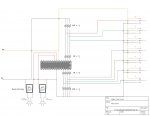
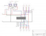
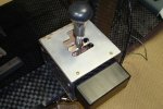
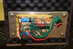
Hello, this is my first project with a PICAXE microcontroller. I am tapping into my Xbox 360 wireless racing wheel and trying to add a gated 6 speed plus reverse shifter. There is a switch at each gate that switches on when the shifter is put into that gear. These switches are connected to the PICAXE28X1, and then the microcontroller determines how many ‘up’ or ‘down’ shifts to send to the paddle shifters.

I’ve attached the code that I’m using. When I run the simulation in the programming editor, the code appears to function correctly. However, when I flash the code to the microcontroller and use it for the shifter, two things happen.

1. The microcontroller does not shift properly. Instead, the two output pins alternate switching high and low infinitely.
2. However, when a gear is engaged (a switch is on), the output pins stop alternating high and low, but nothing else happens.

I’ve tested the whole system with a multimeter and no wires are crossed or anything. So I believe that it is the PICAXE that isn’t working. Anybody know what’s going on with my code?


Code:
symbol current = b0
symbol new = b1
symbol change = b2

init: let current = 1

main: if pin0 = 1 then 
		goto setR
	elseif pin1 = 1 then 
		goto set1
	elseif pin2 = 1 then 
		goto set2
	elseif pin3 = 1 then 
		goto set3
	elseif pin4 = 1 then 
		goto set4
	elseif pin5 = 1 then 
		goto set5
	elseif pin6 = 1 then 
		goto set6
	else
		goto main
	endif

setR: let new = 0
	if new = current then main
	goto calc

set1: let new = 1
	if new = current then main
	goto calc

set2: let new = 2
	if new = current then main
	goto calc

set3: let new = 3
	if new = current then main
	goto calc

set4: let new = 4
	if new = current then main
	goto calc

set5: let new = 5
	if new = current then main
	goto calc

set6: let new = 6
	if new = current then main
	goto calc

calc: if current<new then up
	if current>new then down

up:   let change = new-current
	for b3 = 1 to change
		high 1
		wait 1
		low 1
	next b3
	let current = new
	goto main

down: let change = current-new
	for b3 = 1 to change
		high 0
		wait 1
		low 0
	next b3
	let current = new
	goto main
 

westaust55

Moderator
Welcome to the PICAXE forum.

Late at night here (midnight :cool: ) but try this as a starting point:
Code:
symbol current = b0
symbol new = b1
symbol change = b2
SYMBOL gears = b3


init: let current = 1

Main:

	gears = pins
	new = NCD gears - 1

	IF new = current then main
	  IF current<new then
	  change = new-current
	  for b3 = 1 to change
		high 1
		wait 1
		low 1
	  next b3
	
	ELSE
	  change = current-new
	  for b3 = 1 to change
		high 0
		wait 1
		low 0
	  next b3
	ENDIF
	let current = new
	goto main

One issue may have been that the inputs changed while you were scanning the inputs. bets to grab all the input states and then check agains the snapshot.

Your code could be a lot simpler as per the example (if I got it right) and using the commands available to 28X1 chip.
At least should be the same as what you had.
 
Last edited:

KTarke

Senior Member
You are using normal switches...

Picaxe's manuals (picaxe_manualX.pdf where X = 1,2,3) are the bible...

This time, read manual3 , pages 25,26 ,says the reverend:)

There is told about a thing called bounce.
And maybe it is worth to check, if the pull-up and pull-down resistors are there, and chosen rightly...
(if a inputpin is "floating", results can be odd)

The code is not the only one, that can cause those odd things, check the hardware against manual.
 

BigCat41121

New Member
Thanks for the suggestion to use 'NCD' command - really helped simplify things. :) Here's the updated code that westaust55 helped with. Here again, it works great in the simulation within the program editor, but when implemented into the actual shifter, the output pins don't go high (ever).

If switch bounce is in fact the culprit, I tried adding a pause similar to the one in the picaxe manual as suggested by KTarke. Not sure if I placed it in the correct spot in the code though.

I also tied down the inputs with resistors - 10K and 1K as shown in the manuals. Still no luck. Is there anything else I could try to get those output pins firing?

Code:
symbol current = b0
symbol new = b1
symbol change = b2
SYMBOL gears = b3


init: let current = 5

Main:
	gears = pins
	new = NCD gears-10
	pause 100	'delay for switch bounce
	
	IF new>6 then main

	IF new = current then main
	  IF current<new then
	  change = new-current
	  for b4 = 1 to change
		high 0
		pause 500
		low 0
	  next b4
	
	ELSE
	  change = current-new
	  for b4 = 1 to change
		high 1
		pause 500
		low 1
	  next b4
	ENDIF
	let current = new
	goto main
 

MPep

Senior Member
Please attach a circuit diagram. There may be something that others spot that may be causing problems for you.

Extra: I suspec that the
Code:
high 1; pause 500; low 1
should be changed to
Code:
 high 1; pause 250; low 1; pause 250
thereby creating a clear high-low transition. I suspect that the loop goes soo fast that the pin1 virtually stays HIGH at all times.
 
Last edited:

westaust55

Moderator
Spotted that you had changed a line to
new = NCD gears- 10

checkin in the Programming Editor, I see that the PE v5.2.11 is not simulating the NCD command correctly
even by the manual
let b1 = ncd %00000100 should make b1= 3

but we see b1 = 14 :eek:


Will report this in the Programming Editor section
 

SAborn

Senior Member
I find your switching layout a bit wierd, as i dont see why you have 1/2 of each switch tied to ground, but that should not matter if you are only switching high when the switch is closed.

I would get rid of the 1K resistors as i dont see why they are needed.

The bigest problem i see is you are trying to switch the relays direct from the picaxe and would suspect you are overloading the output pins.

A picaxe will only supply around 20mA output and without knowing what type of relays they are i can only guess they are almost a dead short across the output pins.
A reverse diode across the relay coils would also be advised.
I would use a small transistor between the picaxe and the relay to do the switching.

I dont see any programming circuit shown or other things like reset pullup, crystal, and can only guess these are in place but not shown on a short version schematic.

Disconnect the relays and place a led in their place and see what results you get.
 

BigCat41121

New Member
Thanks for the suggestions. Would a circuit like this work better? I'm not sure if I got the direction of the diodes used to protect against back EMF correct. Thought I better check with the experts before I built it :)

Also, I'm using the 28X1 starter pack to program the PICAXE which is why you aren't seeing any programming circuits in my diagram. The board I'm building has an IC socket for the PICAXE. Kind of hard on the pins to move it between the two but I'm being as careful as I can.
 

Attachments

MPep

Senior Member
No. The transistors are in the wrong position. Put the emitter to 0V, and collector to the coil. The other end of the coil should go to +V.
Diodes are shown with the correct polarity.
 

John West

Senior Member
I'd suggest you put the transistors in the leg of the relay that's closest to ground (earth) - not closest to +5V. When driven by a PICAXE output the NPN transistors will work best there.

The current to turn on the transistor is based on the difference in voltage between the base leg and the emitter leg - and with the transistor mounted as is that voltage would jump all over the place as the relay is turned on and off.

Best to keep the emitter leg of the transistor fixed at ground (earth) potential.
 
Last edited:

westaust55

Moderator
To better help you understand the comments that MPep and John West are giving you, also have a look at PICAXE Manual 3 pages such as 9, 11 and in particular 13 (the later specifically covers relay control).
 
Last edited:

SAborn

Senior Member
I notice in the last schematic bigcat posted, the relays used are reed relays and from the one i have used they have about 10 mA draw so should work without the need for a transistor.

You would need to check the data sheet for the relays used to see their rating but the ones i checked had 500R coil resistance which = 5v/500 = 0.010 mA which is within the picaxe ability.

The earlier schematic did not show reed relays used. Hence the recommendation for transistors to be used.

You will still need the diodes across the relay coils.
 

MartinM57

Moderator
5v/500R = 0.01A = 10mA

...still within PICAXE output current limits, but I thought I'd be the first pedant to point it out ;)
 

BigCat41121

New Member
SAborn and MartinM57 you are correct, the PICAXE can switch the reed relays.

I connected LEDs to the output pins along with the relays and have been doing some testing. What I discovered was weird.

I started by loading my original code onto the PICAXE because I knew that it could switch the relays. The LEDs lit up as well, which confirmed that I had them wired in correctly.

I then loaded the version of code that used the 'NCD' command that westaust55 suggested I use. When the shifter was put into first gear (closing the corresponding switch), the LED connected to the UP output turned on/off five times, and then the LED connected to the DOWN output turned on/off five times. This would repeat infinitely as long as the switch was closed. If I moved the shifter into second gear, the same thing would happen, only there were four pulses. Third gear = 3 pulses, fourth = 2, fifth = 1, sixth = 0, reverse = 6.

I suspect that there is something going wrong with the 'NCD' command and the way that it works with the PICAXE judging by the PE simulation error and my testing. Maybe I'm using it incorrectly in my code?
 

SAborn

Senior Member
Bigcat

Good to hear you have some working results.

As for the "NCD" command i dont know it and have never used it.

I tend to be a more hardware minded person and use code i understand till i nut out the workings of new commands. So unable to comment on your wierd going ons.

Im sure Westy will get his teeth into it and offer some understanding.

If not use code that you do understand and advance as your learning increases.

Good luck.
 

westaust55

Moderator
We know the PE simulator is not using NCD correctly.
I will check with a 40X1 chip tonight and see if that gives correct output using the NCD comamnd. I have used NCD and DCD in the past so maybe use a PE problem.
 

westaust55

Moderator
Okay, after some in Chip testing, I can confirm that the NCD command does work correctly in a 40X1 and would therefore believe the same is true of the 28X1 as used by BigCat.

Therefore where you added a '- 10' after the NCD command, you will need to remove that before that (the -10) part for the program will work correctly within the actual 28X1 PICAXE chip.

The PAUSE 100 as a switch debounce does not do anything for you as the reading of the inputs was done with the line
gears = pins​
at the worse in your application it may take a cycle in the program for the data to be correct

but after the pause use the line
IF new= 0 or new >6 then main​
otherwise it will see all switches open as a gear change
 
Last edited:

BigCat41121

New Member
Spent the last day or so building a new board and messing around the the NCD command. I have found that it does work with the PICAXE, and that the only problem with it is confined to the simulation in the PE.

I also discovered that output 0 has been causing me problems - wont ever switch high. Simply changed my code and moved wires on the board so that I use outputs 1 and 2. Works fine now.

At this point, I'm able to use gears one and two as a sequential shifter. Hopefully in a few days I'll have the entire shifter working. Small victories!! :)
 

westaust55

Moderator
Great to read that your initial problems are resolved and you are well on the way to completion.

With respect to the 28X1 output 0 never switching high, either:
1 there is a wiring fault such as a short to ground (0V)
Say with pin/leg 8 (0V) opposite shorted to pin/leg 21 (output 0) below the chip ,
2 the chip has been damaged
3 both of the above as 1 can lead to 2.
 

BigCat41121

New Member
Given the fact that I'm very inexperienced with these types of projects, I’m sure I unintentionally shorted/damaged that pin. No big deal though.

Finally finished the shifter today – works perfectly. Thanks to everyone who posted and offered advice. It was greatly appreciated :)
 

BigCat41121

New Member
Final code:

Code:
symbol current = b0
symbol new = b1
symbol change = b2
SYMBOL gears = b3


init: let current = 2
	

Main:
	gears = pins
	new = NCD gears	
	
	IF new=0 or new>7 or new=current then main

	IF current<new then
	  change = new-current
	  for b4 = 1 to change
		high 1
		pause 75
		low 1
		pause 75
	  next b4
	
	ELSE
	  change = current-new
	  for b4 = 1 to change
		high 2
		pause 75
		low 2
		pause 75
	  next b4
	ENDIF
	let current = new
	goto main
Attached photos of the shifter and board. The board is attached to the outside of the shifter in the solid black box.
 

Attachments

westaust55

Moderator
And now that you are running, try this version to save even more program space
Code:
symbol current = b0
symbol new = b1
symbol change = b2
SYMBOL gears = b3
SYMBOL direction = b4

SYMBOL up =1
SYMBOL down =2

Init: let current = 2
	

Main:
	gears = pins
	new = NCD gears	
	
	IF new=0 OR new>7 OR new=current THEN main

	IF current<new then
	  change = new-current
	  direction = up
	ELSE
	  change = current-new
	  direction = down
	ENDIF  
	FOR b4 = 1 to change
		high direction
		pause 75
		low direction
		pause 75
	NEXT b4
	let current = new
	GOTO Main
Now if it was not for the NCD command you could drop to a "smaller" PICAXE as well.
 

hippy

Ex-Staff (retired)
Staff member
A suitable NCD for non-X1, non-X2 could be ...

LookDown 1, ( pin7, pin6, pin5, pin4, pin3, pin2, pin1, pin0, 1 ), new
new = 8 - new
 

MPep

Senior Member
Hi BigCat,

Thanks for the photos. Standard rally car shifter arrangement looks great.


Some interesting solutions here.
I have reworked the codes above: 1- to include Hippy's non-NCD variation; and 2- to correct a mistake in WA's code.

In WA's code, 'direction' is declared as being B4. However, both B4 and 'direction' are required for seperate operations/functions.
In the simulator, there were more than 2 output pulse pins being used :eek:. Oops.
Don't worry Westy, a Kiwi will sort it out for you:D.

Try this code, uses a 20M, and only 68/256 Bytes,:
Code:
#picaxe 20m
    
symbol current = b0
symbol new = b1
symbol change = b2
SYMBOL gears = b3
SYMBOL OPpulses = b4
symbol OPpin = b5

SYMBOL up =1
SYMBOL down =2

Init: let current = 2
    

Main:
    gears = pins
    LookDown 1, ( pin7, pin6, pin5, pin4, pin3, pin2, pin1, pin0, 1 ), new
    new = 8 - new    

    IF new=0 OR new>7 OR new=current THEN main

    IF current<new then
          change = new-current
        OPpin = up

    ELSE
          change = current-new
          OPpin = down
    ENDIF  

    FOR OPpulses = 1 to change
        high OPpin
        pause 75
        low OPpin
        pause 75
    NEXT OPpulses
    let current = new
    GOTO Main
MPep.
 
Last edited:

westaust55

Moderator
Good spot MPep. :eek:

Comes from not actually testing the code (did say "try" this = untested)
Also stems from not having all the variables declared with alias at the start and I just assigned the next variable

We can also remove the SYMBOL and statement for the variable "gears" as we are not using that variable any longer so down to:

Code:
SYMBOL current = b0
SYMBOL new = b1
SYMBOL change = b2
SYMBOL OPpin = b3
SYMBOL OPpulses = b4


SYMBOL up =1
SYMBOL down =2

Init: current = 2
    

Main:
    LookDown 1, ( pin7, pin6, pin5, pin4, pin3, pin2, pin1, pin0, 1 ), new
    new = 8 - new    

    IF new=0 OR new>7 OR new=current THEN Main

    IF current<new THEN
        change = new-current
        OPpin = up
    ELSE
        change = current-new
        OPpin = down
    ENDIF  

    FOR OPpulses = 1 TO change
        HIGH OPpin
        PAUSE 75
        LOW OPpin
        PAUSE 75
    NEXT OPpulses
    current = new
    GOTO Main


To take hippy's NCD for non-X1/X2 equation a step further
the syntax for a variable as opposed to hardware pins could use variable b0

so equivalent of
b1 = NCD b0​
would be
LookDown 1, ( bit7, bit6, bit5, bit4, bit3, bit2, bit1, bit0, 1 ), b1 : b1 = 8 - b1​
 

MPep

Senior Member
Good point re "gears".

Redone the program, because initially I could not select 'pin7'.
With this version, you can:
Code:
#picaxe 20m
    
symbol current = b0
symbol new = b1
symbol change = b2
symbol OPpulses = b3
symbol OPpin = b4

symbol up =1
symbol down =2

Init: let current = 2

Main:
    LookDown 1,(pin7,pin6,pin5,pin4,pin3,pin2,pin1,pin0,1),new:new = 8 - new    

    IF new=0 OR new>8 OR new=current THEN main

    IF current<new then
        change = new-current
      OPpin  = up
    ELSE
        change = current-new
      OPpin  = down
    ENDIF  

    FOR OPpulses = 1 to change
      high OPpin
      pause 75
      low OPpin
      pause 75
    NEXT OPpulses
    let current = new
    GOTO Main
 
Top