20X2 4 Digit LED Counter

marks

Senior Member
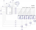
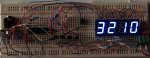
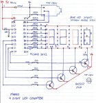
20X2 4 Digit 7 Segment LED Counter

Oh No another Counter
Every one seems to love doing them.

push the button will count from 1 to 9999
and then reset
if your finger can go the distance.

Code:
	'             -- --   -- --   -- --   -- --
	' B0-A       |     | |     | |     | |     |
	' B1-B	
	' B2-C       |     | |     | |     | |     |
	' B3-D        -- --   -- --   -- --   -- --
	' B4-E       |     | |     | |     | |     |
	' B5-F
	' B6-G       |     | |     | |     | |     |
	' B7-         -- --   -- --   -- --   -- --   
	'
	'Display        1       2       3       4
	'Common anode  C.3     C.2     C.1     c.0
main:
let dirsb = %11111111
let dirsc = %10111111
w0=0

start:w1=0

Display:

let b10 = w0 dig 3
if w0 < 1000 then bl10                                       'Zero blanking
lookup b10, (192,249,164,176,153,146,130,248,128,144),b10    '(0,1,2,3,4,5,6,7,8,9)
Dig1:  high c.0 : let pinsb = b10 : low c.3 : pause 1        'Display1 


let b11 = w0 dig 2	
if w0 < 100 then bl11                                        'Zero blanking
lookup b11, (192,249,164,176,153,146,130,248,128,144),b11    '(0,1,2,3,4,5,6,7,8,9)
Dig2:  high c.3 : let pinsb = b11 : low c.2 : pause 1        'Display2 
	
	
let b12 = w0 dig 1	
if w0 < 10 then bl12                                         'Zero blanking
lookup b12, (192,249,164,176,153,146,130,248,128,144),b12	 '(0,1,2,3,4,5,6,7,8,9)
Dig3:  high c.2 : let pinsb = b12 : low c.1 : pause 1        'Display3 


let b13 = w0 dig 0	
lookup b13, (192,249,164,176,153,146,130,248,128,144),b13    '(0,1,2,3,4,5,6,7,8,9)
Dig4:  high c.1 : let pinsb = b13 : low c.0 : pause 1        'Display4 
	
if pinc.6=0 then start                                       'reset ready for next count
 
s1:let w1=w1+1                                               'ignores button bounce
if w1>1 then display

if w0>9998 then main                                         'Reset after 9999 reached
let w0=w0+1 goto display                                     'Add count by 1 

bl10: let b10 =255  goto Dig1                                 
bl11: let b11 =255  goto Dig2
bl12: let b12 =255  goto Dig3
 

Attachments

Last edited:

westaust55

Moderator
Hi Marks,


First Point:
Looking at your circuit, the BC547 transistors have an Ic rating of 100mA.

With 150 Ohm resistors in series with the mentioned LED Vforward of 3V that equates to 12 mA per segment.
For the digit "8" there are 7 x 13 mA = 91 mA so that is okay considering the multiplexing.


Next, for transistor Vce into saturation with Ic = 100mA, you need Ib = 5mA and Vbe = 0.9 Volts

For the resistor between the PICAXE and transistor base
Vres = 5 - 0.9 = 4.1 Volts
To enable 5mA you need a max resistance of 4.1 / 0.005 = 820 Ohms

Thus with a 10 kOhm resistor in the transistor base circuit you are not driving the transistor into saturation and thus can be creating extra heat in the transistors and limiting the current in the LED circuits.


Therefore, I suggest you reduce the transistor base resistance accordingly.


Second point:
I see you have a stereo programming socket mounted on the breadboard.
The pins on these stereo sockets are rather short and many before you have had problems becasue the socket does not make good electrical conenction with the breadbaord internal connections.

Be aware of this and maybe consider some form of adapter for mounting the stereo socket onto a breadboard.
 

marks

Senior Member
Hi Westaust55,
dam your good !
almost frightened to add any more threads lol.
Had to edit my circuit post actually its a BC557B PnP transistor.
not making excuses just used some parts i had laying around.
I hope i'm keeping you entertained i really do appreciate your valued input!
looks like your teaching me do's and dont's not just lookup tables lol.

Current draw of a digit 8 lit is actually only 12ma max at 5v (when multiplexed)
I would say about 1.7 ma per segment.

At only 12ma per port you could do away with the transistors and drive them direct
i might try this later of course you would have to alter the code.
really they are there for protecting the picake chip when programming.

I think you are quite correct a 1000 ohm would be more appropiate
especially if you want the display brighter you would also have to reduce the 150 ohm
resitors to 100 ohm. (transistor collector current 20ma)
maximum total circuit draw all digits lit 8888 82ma almost double original circuit
you could reduce the 100 ohm more if wanted but i find the display quite bright!

And yes you are right about that socket too i occassionly have to push on it
to get it to work.
thanks again!
 
Last edited:
cheers mark, this example helped me, a new guy to the picaxe chips, understand how to make a counter :)

quick question does the picaxe 20x2 have the ability to save bits; as i need the counter to save the number and then load it when the next circuit is turned on

cheers
 

hippy

Ex-Staff (retired)
Welcome to the PICAXE Forum.

Yes, you can save and restore data on all current PICAXE - Check out the WRITE and READ commands in Manual 2.
 

BeanieBots

Moderator
casper,
As Hippy states, any PICAXE can save data to be restored next time power is restored, but be careful. Don't save the number every time it changes if it is a frequent change because EEPROM has limited life-span (~100,000 dependign on type) and you could destroy it.
 

BeanieBots

Moderator
Just start a new thread.
My PM box is often full and I don't always get around to reading them.
A new thread will get you a much wider audience and replies.
 

sodeaf

Senior Member
Hey Guys, Just curios to know if there is information on how this actually works. I am new to picaxe when it comes to more complicate things..
I guess in regards to:
lookup b10, (192,249,164,176,153,146,130,248,128,144),b10 '(0,1,2,3,4,5,6,7,8,9)

What exactly is going on here? Is the picaxe reprogrammed to know what this commands mean? and What output you are using? If so where do I find this information regarding this? I looked over the manuals to try and find it without any luck..
Are these symbol commands, or does picaxe read this as being the output pins?
B0-A ??
B0-B ??

I would appreciate and clarification to this.. Instead of just copying and pasting the code, I would rather understand it from top to bottom.. I have used picaxe in many basic projects but have yet to venture into something like this.

Thanks

Steve
 

nick12ab

Senior Member
Hey Guys, Just curios to know if there is information on how this actually works. I am new to picaxe when it comes to more complicate things..
I guess in regards to:
lookup b10, (192,249,164,176,153,146,130,248,128,144),b10 '(0,1,2,3,4,5,6,7,8,9)

What exactly is going on here?
It converts the value in b10 (i.e. 0 to 9) to bit patterns for the 7 segment displays.
 

marks

Senior Member
Hi sodeaf,
Hopefully this clears things up!

Code:
let dirsb = %11111111                                        '  make portb all outputs)
let dirsc = %00111111


temp:

Dig1:   let pinsb = 249 : low c.3 : pause 1 : high c.3       'Display1       1
 
                                      
Dig2:   let pinsb = 144 : low c.2 : pause 1 : high c.2       'Display2       9
			
Dig3:   let pinsb = 156 : low c.1 : pause 1 : high c.1       'Display3       o

Dig4:   let pinsb = 198 : low c.0 : pause 1 : high c.0       'Display4       C


goto temp

'      program must loop and always be continuous with out pausing

'     pinsb =(value determines whats displayed   255  Clear display    (   )
'                                                  0  full display     ( 8.)
'                                                249  will display     ( 1 )
'        low c.3   ( turn on  transistor 1)
'        pause 1   ( on period)
'        high c.3  ( turn off transistor 1)

'      How we work out the value of portB pins for our segments

        '                       a
	'                     -- --  
	' B.0 - A  ( 1 )     |     | 
	' B.1 - B  ( 2 )    f       b
	' B.2 - C  ( 4 )     |  g  | 
	' B.3 - D  ( 8 )      -- --   
	' B.4 - E  ( 16)     |     | 
	' B.5 - F  ( 32)    e       c
	' B.6 - G  ( 64)     |  d  | 
	' B.7 - dp (128)      -- --  o 
	
	' adding all the numbers up turns off all segments (CommonAnode Display)
	' if we want to display a  (C)   we turn off segments (  b   c   g    dp )   add values
      '                                            example  (  2 + 4 + 64 + 128)  = 198
 

sodeaf

Senior Member
Hey Marks

I really appreciate the explanation. It is starting to make sense. I have a 4 Digit 7 Segment on its way.. So I will play around with it and see if I can get her to work.. So I guess it would be best to dedicate a specific 20M2 just for this and use another for other computing. The uC running the display must not have any other pauses in it or it could start to flicker I assume. Or I guess I could run to "Starts" at 8Mhz.. ??

All I need to do is have 2 inputs,, "Clear" and "Count up"

Thanks

Steve
 

sodeaf

Senior Member
Hey Guys.. Been looking this over and over.. I guess I cannot use the 20M2 for it does not support the "DIG" command.. Is there an alternative to this? Any Ideas? As well I was planning on using Common Cathode displays. Thanks


Steve
 

hippy

Ex-Staff (retired)
I guess I cannot use the 20M2 for it does not support the "DIG" command.. Is there an alternative to this?
The BINTOASCII command does very similar to DIG, plus it's possible to extract numeric digits from a number by dividing by an appropriate power of 10 and doing a modulo 10 ...

b2 = w0 DIG 2

b2 = w0 / 100 // 10
 

sodeaf

Senior Member
The BINTOASCII command does very similar to DIG, plus it's possible to extract numeric digits from a number by dividing by an appropriate power of 10 and doing a modulo 10 ...

b2 = w0 DIG 2

b2 = w0 / 100 // 10
Hey Hippy... Thanks for the info.. Last night I was able to modify the code and use a 40x2 to run my 4 digit common cathode display.. It works awesome.. Its nice to see things working!

I will have to change somethings to see if I can get that to work... Is there any other info you can suggest I can read.. I looked in the manual.. but it wasn't very specific.. Or if you could give me a quick sample.. (i know you did already) but I am still confused.. )

Thanks..

I really do appreciate this.. with out you guys I would be no where with this..
Thanks

Steve
 

sodeaf

Senior Member
I think I might understand this actually..

Lat night in the program editor I tried this program with the "Dig 1,2,3 etc" It wouldn't allow me to program the 20m2 because of the "dig" command.. So i just removed the command and in the simulator it worked great until I got to a double digit number..
But If i replace the "dig" command with what Hippy suggest then that should work. b2=w0 / 10 for digit 2, b2=w0 / 100 for digit 3 and so on? I cannot try this right now for I am at work.. But in theroy I think it works.. I will mess around..

Thanks again..

(I don't know if it even makes sense trying to get the 20m2 to do this, for the 20x2 is cheaper. ) but all I have for chips is the 20m2 and 1 x 40x2... I know why! It's all about the challenge..
 

marks

Senior Member
20m2 4 Digit LED Counter (commonCathode)

Code:
''# picaxe20x2
'# picaxe20m2
	'              -- --   -- --   -- --   -- --
	' B.0-A       |     | |     | |     | |     |
	' B.1-B	
	' B.2-C       |     | |     | |     | |     |
	' B.3-D        -- --   -- --   -- --   -- --
	' B.4-E       |     | |     | |     | |     |
	' B.5-F
	' B.6-G       |     | |     | |     | |     |
	' B.7-         -- --   -- --   -- --   -- --   
	'
	'Display         1       2       3       4
	'CommonCathode  C.3     C.2     C.1     C.0
	
	SYMBOL pushbutton    = PINC.6
	SYMBOL display1      = C.3     
	SYMBOL display2      = C.2
	SYMBOL display3      = C.1
	SYMBOL display4      = C.0
	
	SYMBOL number        = B0
	SYMBOL push          = B1 
	SYMBOL counter       = W1 'b2,b3
	
LET dirsb = %11111111
LET dirsc = %10111111

Main: counter = 0

Start: push = 0

Display:
LET number = 0 : IF counter < 1000 THEN Dig1                            'Zero blanking 
LET number = counter / 1000                                        
LOOKUP number, (63,6,91,79,102,109,125,7,127,111),number           '(0,1,2,3,4,5,6,7,8,9)
Dig1:  LOW display4 : LET pinsb = number : HIGH display1 : PAUSE 1 'Display1 

IF counter < 100 THEN Dig2                                              'Zero blanking
LET number = counter / 100 //10
LOOKUP number, (63,6,91,79,102,109,125,7,127,111),number           '(0,1,2,3,4,5,6,7,8,9)
Dig2:  LOW display1 : LET pinsb = number : HIGH display2 : PAUSE 1 'Display2 
	
IF counter < 10  THEN Dig3                                               'Zero blanking	
LET number = counter // 100 /10	
LOOKUP number, (63,6,91,79,102,109,125,7,127,111),number	       '(0,1,2,3,4,5,6,7,8,9)
Dig3:  LOW display2 : LET pinsb = number : HIGH display3 : PAUSE 1 'Display3 

LET number = counter // 10	
LOOKUP number, (63,6,91,79,102,109,125,7,127,111),number           '(0,1,2,3,4,5,6,7,8,9)
Dig4:  LOW display3 : LET pinsb = number : HIGH display4 : PAUSE 1 'Display4 
	
IF pinc.6 = 0 THEN Start                                           'reset ready for next count
 
INC push                                                           'ignores button bounce
IF  push > 1 THEN Display

INC counter                                                        'Add count by 1 
IF  counter > 9999 THEN LET counter = 0 : ENDIF                    'Reset after 9999 reached
GOTO Display
 

Attachments

Last edited:

hippy

Ex-Staff (retired)
Looks good and I'm assuming it works as desired.

There are a couple of ways you could tidy up the code to make it easier to follow, and reduce code size - though neither are a necessity.

Code:
If w0 < 1000 Then
  b10 = 0
Else
  b10 = w0 / 1000
  lookup b10, (63,6,91,79,102,109,125,7,127,111),b10    '(0,1,2,3,4,5,6,7,8,9)
End If
low c.0 : let pinsb = b10 : high c.3 : pause 1        'Display1
And similar for the other digits; that saves having to follow 'goto' around the place, so-called 'spaghetti coding'.

You could also use b10 in all those conditions, and move the LOOKUP into a subroutine and called with a GOSUB to save program space.

A very minimal program, but perhaps more complicated to follow is to have a single routine which can have which digit to show and which pin to pulse specified (untested) ...

Code:
Main:
  w0 = 1234
  w1 = 1000 : b4 = C.0 : Gosub OutputDigit
  w1 = 100  : b4 = C.3 : Gosub OutputDigit 
  w1 = 10   : b4 = C.2 : Gosub OutputDigit
  w1 = 1    : b4 = C.1 : Gosub OutputDigit
  Goto Main

OutputDigit:
  If w1 > 1 And w0 < w1 Then
    b10 = 0
  Else
    b10 = w0 / w1 // 10
    lookup b10, (63,6,91,79,102,109,125,7,127,111),b10    '(0,1,2,3,4,5,6,7,8,9)
  End If
  low b4 : let pinsb = b10 : high b4 : pause 1
  Return
There's nothing wrong with what you have - the most important thing is a program which works - and that's just given as an example, food for thought.
 

sodeaf

Senior Member
Thanks to Hippy and Marks.. You guys have gone well out of your way helping me here.. Just to know you took the time to give those examples.. I really appreciate it.. Thanks again..

I am really starting to understand all this.. and it does make sense.. I just spend some time learning.. what b10 = w0 / 100 //10 really does..
So if the number was 5745
what is really happening is 5745 / 100 - 57.45 and by adding //10 means only use the "remainder" of 10 = 7 (sorry dumb question, but I want to really understand this.. ) is the //10 asking to only use the 2nd digit, or is there some math there..

Just never been good at the math stuff.. I strive to try and actually understand.. for next time.. just want to make sure I am on the right track..

Thanks

Steve

As well considering you have helped me with the program that I can use on the 20m2.. Could I use 2 program slots at 8mhz and run the display off one main, and a little "check inputs" program on another without any trouble? Its just that I might need to use a couple pause commands which I cannot do or I will start to get flicker..
 

hippy

Ex-Staff (retired)
I am really starting to understand all this.. and it does make sense.. I just spend some time learning.. what b10 = w0 / 100 //10 really does..
So if the number was 5745
what is really happening is 5745 / 100 - 57.45 and by adding //10 means only use the "remainder" of 10 = 7 (sorry dumb question, but I want to really understand this.. ) is the //10 asking to only use the 2nd digit, or is there some math there..
Pretty much, 5745 / 100 = 57 because the PICAXE 'doesn't do decimal fractions', rounds down towards zero, and then the //10 gets the remainder of 57/10=7 so that's pulled a single decimal digit out of the number.

As well considering you have helped me with the program that I can use on the 20m2.. Could I use 2 program slots at 8mhz and run the display off one main, and a little "check inputs" program on another without any trouble?
Possibly but you could be complicating things quite considerably and could hit trouble. To start with, if you can keep it all in a single slot, you'll probably have an easier time of it.

No offence meant and I don't mean to discourage at all, but it can be like taking on the high board when you haven't mastered diving off the low board. The more you can get familiar with before moving on the easier moving on becomes.

Added : Just realised you said "slots" but meant "tasks"; only the X2 have slots, only M2's have multiple tasks. I think the same applies but multi-tasking isn't too difficult. It's probably best to try some simple experiments with multi-tasking first.
 

sodeaf

Senior Member
Awesome..

Can't wait to get home and start playing around..

I appreciate the clarification..

Once I get the counter working.. I need to build a 2 digit 15 min countdown timer.. I plan on using the same style of code in the reverse order I guess and only for 2 digits. I will be relying on the 20m2 to keep some what "good time" at 4 MHz they should be petty close.. For what i am doing it doesn't have to be 100%.. Close would be nice.. I will time the "timer" to see how accurate it is tonight.. I know I could use a ds1307 i believe its called.. there is one on my picaxe board.. have yet to touch it..

Thanks Again..
 

sodeaf

Senior Member
Hey Guys,

Thanks again for all your help... I have been able to complete the code for the current project I am working on.. I had used a couple old 7 segment displays that I am unable to find the data sheet for (they are very dim, i think its due to the old cheap technology... or there forward voltage is probably much higher then i am supplying). So I am in the process of trying to find some the are going to work for the job. I have read a lot about people having issues with brightness? If i were to buy a couple displays that have a high mcd output then this should not be a problem.. I just want to make sure I don't have to use transistors for the output to digits.. considering it is continuously turning on then off each segment individually then each output only have to power one single led of a segment at each time. If I keep the current below 20ma then there should be no issue, or reason to include pnp transistors on those outputs?

As well is there a way to include the decimal point on b.7.. considering it is not being used at the moment.. ? I am using a differnt output at the moment..

Display:
let b8 = w1 // 100 /10 'Clock digit 1
if w1 < 10 then bl08 'Zero blanking
lookup b8, (63,6,91,79,102,109,125,7,127,111),b8 '(0,1,2,3,4,5,6,7,8,9)
Dig1: low c.0 : let pinsb = b8 : high c.5 'Display1
if b23 = 1 then high d.7 endif 'Display decimal every other second
pause 1

Thanks again for all your help.. it has been a great learning experience.
 

sodeaf

Senior Member
Hey there,

I got the decimal to work.. pretty easy.. I guess the only other question I have is the timing accuracy..

Now my entire program only has 6 pause 1 commands.. so .006 seconds total.. how much time delay is there in running the program itself? Is this something you kinda keep adjusting until your minutes and seconds are close to real time? (eg my "167" number below)
I mean if I count loops threw my program which has 6 pause 1 commands.. let w0=w0+1 ..... then.... if w0=167 then incW4.. 167 x .006 = 1000.... you would think every time w4 is incremented a second would have been reached.. or close to it..
That doesn't seem to be the case.. it off more the 40%
I am running at 8MHz on a 40x2.. Just trying to clarify this.. thanks..
 

marks

Senior Member
Hi sodeaf,
slight rewrite of code post 18 as a newbie was the first time using LOOKUP TABLES thanks to Westaus55.

with multiplexing we are time sharing the more displays we introduce the dimmer it will become
I assume your trying to drive six of 'em.

the 20m2 can source 65ma and sink 85ma so more advantageous to use commonanode displays
as yourve discovered select high intensity ones.
for brighter its easiest to increase voltage to our display.

more complicated code 16 mhz works well and replace LOOKUPTABLES with READ or READTABLE thanks hippy.
for timing use TIME or TIMER.
and a few threads of interest checkout countdown timer and others lol. http://www.picaxeforum.co.uk/showthread.php?16020-20X2-4-digit-7-segment-Countdown-timer
http://www.picaxeforum.co.uk/showthread.php?17505-20x2-led-clock-6-digit-7-segment-ds3231-rtc-ds18b20
Code:
# picaxe20x2
'# picaxe20m2
	'              -- --   -- --   -- --   -- --
	' B.0-A       |     | |     | |     | |     |
	' B.1-B	
	' B.2-C       |     | |     | |     | |     |
	' B.3-D        -- --   -- --   -- --   -- --
	' B.4-E       |     | |     | |     | |     |
	' B.5-F
	' B.6-G       |     | |     | |     | |     |
	' B.7-         -- --   -- --   -- --   -- --   
	'
	'Display         1       2       3       4
	'CommonCathode  C.3     C.2     C.1     C.0
	
	SYMBOL pushbutton    = PINC.6
	SYMBOL display1      = C.3     
	SYMBOL display2      = C.2
	SYMBOL display3      = C.1
	SYMBOL display4      = C.0
	
	SYMBOL number        = b0
	SYMBOL push          = b1 
	SYMBOL counter       = W1 'b2,b3
TABLE (63,6,91,79,102,109,125,7,127,111,0) '(0,1,2,3,4,5,6,7,8,9,blank)	
LET dirsb = %11111111
LET dirsc = %10111111

Main: counter = 0

Start: push = 0

Display:
LET number =10 : IF counter < 1000 THEN Dig1                            'Zero blanking 
LET number = counter / 1000                                            
Dig1:  LOW display4 : READTABLE number,pinsb : HIGH display1 : PAUSE 1 'Display1 

IF counter < 100 THEN Dig2                                              'Zero blanking
LET number = counter / 100 //10
Dig2:  LOW display1 : READTABLE number,pinsb : HIGH display2 : PAUSE 1 'Display2 
	
IF counter < 10  THEN Dig3                                              'Zero blanking	
LET number = counter // 100 /10	
Dig3:  LOW display2 : READTABLE number,pinsb : HIGH display3 : PAUSE 1 'Display3 

LET number = counter // 10	
Dig4:  LOW display3 : READTABLE number,pinsb : HIGH display4 : PAUSE 1 'Display4 
	
IF pinc.6 = 0 THEN Start                                           'reset ready for next count
 
INC push                                                           'ignores button bounce
IF  push > 1 THEN Display

INC counter                                                        'Add count by 1 
IF  counter > 9999 THEN LET counter = 0 : ENDIF                    'Reset after 9999 reached
GOTO Display
 
Last edited:

sodeaf

Senior Member
Hey Marks,

Thanks for the input... I see you change the code around a bit.. What is really the difference..I mean what are you gaining by relocating the lookup function. I mean both programs or "Code" will do the same thing. If one better then the other? I have completed my project code, and is similar based on your first posting. I will change it if there is a benefit.. I think there is probably 100's of different ways to do the same thing..
I am going to use transistor on both he segments and digits... so current should not be an issue..
I appreciate your time.. and look forward to your answer.
 

sodeaf

Senior Member
Hey Marks..

OK I have been studying your new code.. I must say.. very nice.. and very interesting at the same time.. Remember I am a newbie.. so my questions might be little stupid... But I understand the whole thing.. other then 2 little parts..

Why does it label Display1 = C.1 (A constant???????????)
but if you did this instead Display1=pinC.1 (in becomes a variable)

Is a constant defined as something you wont ever change.. ie.. Always an output pin... so you define that as C.1 instead of pinc.1

I tried ready about it.. but I am confused.

2nd
----------------------------------------------------------------------------------------------
Display:
LET number =10 : IF counter < 1000 THEN Dig1 'Zero blanking
LET number = counter / 1000
Dig1: LOW display4 : READTABLE number,pinsb : HIGH display1 : PAUSE 1 'Display1
-----------------------------------------------------------------------------------------
Let number = 10 ... How does that work.. what does the `10`` indicate to the table..

And I just noticed that

SYMBOL counter = W1 'b2,b3

Why `b2,b3 just curious... Does w1 use b2 and b3 in memory.. can you not use w1 separate from b2,b3

Sorry for all the detail.. I just really want to understand how a pro does this stuff... I am learning a ton here.. and I cant thank you enough..

Steve
 

sodeaf

Senior Member
Hey Guys.. Sorry for all the posts..

I answered my own questions on the w1 b2,b3 thing.. I realize that if you are using a word variable.. that it will utilize the the corresponding byte variables. All makes sense.. as well the let number = 10.. is then `blank`hence the last spot in your table... I was not counting from `0`.. hahah newbie mistake..

I am now using a 40x2 chip... because of all the inputs and outputs required.. a 28x2 will not work... from what I see in the maunals the 40x2 does not support the table command.. But I think I could use the lookup in then same manner.. I will have to have a look when I get home..

Well I am still trying to find the answer to why the program editor calls something a constant vs variable.. I would like to clarify this.. I have searched for it a100 times..
Found this nifty thing... https://www.jameco.com/webapp/wcs/stores/servlet/Product_10001_10001_1762681_-1
will come in handy for what I want to do..
Thanks again..
 

hippy

Ex-Staff (retired)
Well I am still trying to find the answer to why the program editor calls something a constant vs variable.. I would like to clarify this.. I have searched for it a100 times..
I'm not quite sure I've understood the question but it's something that is common to most programming languages; a constant is a fixed value which cannot be changed, a variable holds a value which can be changed and doesn't necessarily give the same value each time when used.
 

sodeaf

Senior Member
Yeah I get that.

But in program editor...

If you type:

symbol display1 = C.1 - It makes it a constant.. well that's where is shows up in the side panel
symbol display1 = pinC.1 It makes is a variable.

Is this because by typing C.1 indicated you plan on not changing that pin from an output to input during a program?
and if you use pinC.1, you could have the option to change it's status threw out the program?

That's all I need to clarify..

Thanks

As well Considering I am using the 40x2.. Can I use the lookup command in the same way u use a Table Command?
 

hippy

Ex-Staff (retired)
I've used C.2 instead of C.1 because it makes it easier in the following -

C.2 is a pin identifier so it's a permanently fixed value, constant.

pinC.2 is a variable, holding the value of the input pin C.2, or being set to a value to control the output level of pin C.2 ( depending on how it is used ).

If you did "HIGH pinC.2" ( and it didn't throw a syntax check error ) it would be the same as "HIGH 0" or "HIGH 1" depending on the level actually applied to input pin C.2 - It wouldn't actually set the level of output pin C.2
 

sodeaf

Senior Member
Hey Guys.. Thanks again for all your help.. I have finally completed my design.. and about to start designing my PCB..
I am using 8 x 7 segment displays off a 28x2.. 4 are for a countdown clock, and 4 are a pulse counter.. They are common Cathode displays
All digits run off Port C, to a uln2803 NPN transistor array. I have been running the segments direct from the Port B.. It seems to be working fine. But I don't want to over load the output pins. So I was wondering do I really need to add 8 PNP transistors?
I am using 220 Ohm resistor from output pins to segments. Considering each output Pin is only powering One "LED".. Although the ratings of the segments say up to 30ma for Continuous forward current per dice..

I am using 2 x Double Red and 1 x 4 Blue

2seg.jpg4seg.jpg

If you could please give me some pointers would be great..I did measure the current draw of the entire project on breadboard and it was around 80ma - 130 ma..

Thanks.. Steve
 

marks

Senior Member
Hi sodeaf,
luckily your using 28x2 just had a quick look at the elect specs should handle this easily.
 

sodeaf

Senior Member
Hi sodeaf,
luckily your using 28x2 just had a quick look at the elect specs should handle this easily.
Where do you find the specs you speak of?

Thanks again.. I am very happy I don't need to add all those transistors..
 

sodeaf

Senior Member
Hey Marks,

Just to confirm.. I can hook up the segments directly to out pins of the 28x2..No need to use transistors?.. Only need transistor for the digit it self..

Thanks..
 

marks

Senior Member
Hi sodeaf,
If we click on Manuals at the top, we can then click on Base Microcontroller Datasheet.
this shows us the 28x2 is a PIC18F25K22
http://www.microchip.com/wwwproducts/Devices.aspx?dDocName=en546240
or google it lol.

Its a good idea like you've done to start with 220 ohm resistors from the outpins to the seqments
and just use a transistor for the commonAnode or commonCathode on the display digit.
You'll find transistors much more efficient (brighter) than using a uln2803 or udn2981 or output of a picaxe.

With 20x2 I've used 100ohms resistors with blue Anode displays and have found this to be
indestructable even when stuck on one digit or badly coded lol!
And use this to good effect in a menu system for when a button is pressed the digit gets brighter.
 
Last edited:

sodeaf

Senior Member
Hey Marks,

Thanks for the input.. I have designed the setup around the ULN2803 I guess because of the nice package it comes in.. I don't have to mess with resistors and such.. But i guess the draw back to that is.. Not as bright.. Now you have got me thinking.. Do I change out the uln for 8 separate transistors... ??

Umm...

Thanks again..

As well I was checking the current draw of the entire project... and it was around 100 MA... I still thought that was high.. So i removed everything from he Picaxe bread board and realized the board itself has a 40-45 Ma draw with no uC on it.. So I guess my actual setup is around 50-60 ma..

Thanks

Steve
 
Top