Picaxe Ditch light controle issue's

krogerssolar

Senior Member
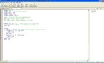
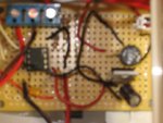
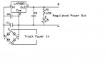
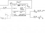
Hi guys I'm new to the Picaxe and to the Forum. I have a few question i ordered some 08M Picaxe for a G Scale Train project to make flashing Ditch Lights on three locomotives. the programing went well got the flash down with the help of http://www.trainelectronics.com/artcles/ditch_lights/index.htm Dave Bodnar http://www.trainelectronics.com/ART5700TrainEngineerRevolution/AUX-2-PICAXE/index.htm the issue im having which im not really sure out to trouble shoot is when i hook up to my battery pack of 20V connect up my 20v to 5v regulator and then connect that to the picaxe it powers up fine when i connect my locomotive up and connect the trigger wires to it just starts flashing and i can not stop it until disconnecting one or the other from the battery. it seem to work ok on my current project working off of 4 AAA batteries my other unit not so well what i cant figure out is where im getting signals or Resistance from on my other unit i see issues from the sound card. On this one there is no sound yet i added a 470ohm resistor on my incoming + line to my 5v ps and that stopped it from going into flashing but it got hot not good anybody have any clue for me I'm not a good electronics geek but i will try and provided as much info as i can
 

Attachments

Last edited:

BeanieBots

Moderator
Welcome to the forum.

Value of C1,2 & 3 ?

It may have just fallen off your diagram, but do you have the 10k part of the download circuit fitted?
 

krogerssolar

Senior Member
yes i do in this case the ps and the picaxe are all on one pcb in the online specs im to put the 10k to +5v when i did that it just triggered the command to flash when i put the 10k down to 0v or gnd it stopped but as i wire it to a Aristo Craft Revolution Rec for better words it gose nuts stays flashing when i have the locomotive power and light/picaxe power tied. until i unwire the trigger wire wich on the Rec side is just a open collector as im told i have no idea what that is

sorry misread the first part c1 is a 1000uf c2 and c3 are 0.1uf or another one i have done use's 100mfd and a 0.1mfd for the 5v ps

also it shows i can wire in the download circuit which o don't have it i have the picaxe on a ic socket for some reason when i would solder it to the pcb it wouldn't work right only one of my two leds would light when its on the ic socket it works. i program the Picaxe on a test breadboard with a usb download cable
 
Last edited:

BeanieBots

Moderator
Any chance you could use some punctuation? I genuinely found that almost impossible to follow with one sentence flowing straight into the next.

Sounds like you have a 10k pull-up on the input which is driven by an open collector. That's fine.
I can't be too sure from your description but it also sounds like you DO NOT have the full download circuit. If that is correct, then that is your problem. A 10k pull-down on the download is ESSENTIAL for correct/reliable opperation.

100uF is not enough for raw rectified AC into a load of several 10's of mA.
The ripple will make its way through the regulator.
Just a bare PICAXE would probably be OK but as soon as an LED comes on, it is likely to reset.
 

krogerssolar

Senior Member
sure this may sound dumb. may i ask what is the download circuit im not sure what that is or how it works. what would be my best plain for a high dc voltage to low voltage drop be something that can handle reverse in polarity mainly.
also dose the main diagram make any sense on how to wire the picaxe ie i don't get why the 10k is to go to +5v. unless in my wiring i have it backward or wrong. any idea's im not really sure what i should try.
 

manuka

Senior Member
Suggest you in intially "ditch" those 4 xAAA & 7805! You need several volts overhead on the 78xx family anyway. As PICAXEs are rated for ~3-5.5V,perhaps simply use 3 x AAA initially- 08M layouts here (& schematic here) ALWAYS work.

I must move in sheltered circles,as that "ditch light" term was quite unknown. However a Google informs that they're normally steady burn, and it's the crossing lights that flash. Stan.
 
Last edited:

krogerssolar

Senior Member
Stan you are right on the google search they are on steady until the horn is blowing then they will flash for a period of time then go back to steady. my issue is im getting unknown issues with my setup one install i did using my AAA pack make its work ok when i power up my locomotive and give it a good voltage i cant trigger the picaxe for its command. my other which are in testing/mounting stage if i hook up to my battery pack of 20volt into the voltage regulator the Picaxe goes nuts starts flashing with out me triggering it from my receiver. not sure if im not hooking up the picaxe right or what im doing wrong.
 

lanternfish

Senior Member
Hi

Reading your posts I think you should closely follow the circuit provided in the second article you linked to. Most importantly that the Revolution and Picaxe share a common ground.

Cheers
 
picaxe railroad

I agree u should check to see that they both have a common ground. I am a nscale model railroader and have several picaxe circuits on it. I have also found that tying pin 2 to ground and sometimes a pretty large capacitor are needed on locomotive circuits. Dirty track and fluctuating voltages will make a picaxe do crazy things. If you are running dcc these things are a must. Dc is a little more forgiving.
 

BeanieBots

Moderator
If DCC is present, then much more will be required by way of supply filtering.
I'd suggest the use of inductive decoupling. Placing low ESR caps either side of it and a low R right up front.
 
DCC

All I have is bridge rectifier and large cap on the output and have not had any problems. Space is such an issue in N scale that I had to break everything down to the basics. Most decoder circuits are this way there are several examples.
 

krogerssolar

Senior Member
mine are mainly G scale which are big and long so no space issue its just a matter of the voltage and what caps i should be using for the regulator. im guessing that is my issue when i tie the locomotive and the picaxe to the same bat and only tie one collector wire to it not the ground it also could be that i didn't wire the picaxe right. i didn't wire on the diagram like it said to put the 10k to +5V i went to -0V side every time i went to +5v it starts its command and dose not stop the only thing missing from my setup is the DB-9 connector would that make a difference.
 

SAborn

Senior Member
Do you have a diode across the supply rail to stop back emf from the motor in the locomotive.
I think the problem is coming from the emf.
Put a diode in reverse across the +/- wires supplying the 5 volt reg.

Electric motors dump nasty voltage spikes into the power wires and micros are very unliking of this.

Easy and worth a try.
 
input

After reading your link I think the problem is in your input wiring. It says that while the output of your decoder is on lights will be off and vis versa. If you have resistor tied to ground and then auxillry goes to ground it will never com on. If you tie it to 5v it will stay on until you activate the auxilary. The aux. needs to be on all the time except when you want lights on. Or program in the picaxe needs changed to reflect the input.
 
Last edited:

BeanieBots

Moderator
I agree with djbillyd007.
Your input is stated as open collector.
That means you MUST connect the 10k pull resistor to +5v or you have no input. If that is activating when you don't want it to, then the logic in your code is inverted.
 

krogerssolar

Senior Member
this is the code that im using

REM d.Kevin Ditch Lightsrev1
REM ditch light experiment
SYMBOL led = 2
SYMBOL temp = w0 'for/next variable
SYMBOL Rate = b8
SYMBOL skip = b9
SYMBOL loop1 = b10
SYMBOL trigger = pin3

rate = 20'adjust these two variables to
skip = 30 'change the speed of flashing
REM higher rate = slower flash
REM higher skip = faster rise/fall of flash.


top:
PWMOUT led, 255, 512 'both lights on at same level
if trigger=1 then flash: 'if horn go to flash
GOTO top:


flash:
FOR loop1 = 1 TO 50 'change this for more or fewer flashes
FOR temp=0 TO 1023 STEP skip
PWMOUT led, 20, temp
PAUSE rate
NEXT temp

FOR temp=1023 TO 0 STEP -skip
PWMOUT led, 0, temp
PAUSE rate
NEXT temp
NEXT loop1
GOTO top:
 

Attachments

Last edited:

krogerssolar

Senior Member
what dose that mean trigger =0 or trigger =1 i know it must be looking for something just not sure what. is that saying a high voltage trigger or low voltage trigger or am i way off on what it means
 
Program change

REM d.Kevin Ditch Lightsrev1
REM ditch light experiment
SYMBOL led = 2
SYMBOL temp = w0 'for/next variable
SYMBOL Rate = b8
SYMBOL skip = b9
SYMBOL loop1 = b10
SYMBOL trigger = pin3

rate = 20'adjust these two variables to
skip = 30 'change the speed of flashing
REM higher rate = slower flash
REM higher skip = faster rise/fall of flash.


top:
PWMOUT led, 255, 512 'both lights on at same level
if trigger=0 then flash: 'if horn go to flash THIS IS THE LINE I CHANGED FROM 1 to 0
GOTO top:


flash:
FOR loop1 = 1 TO 50 'change this for more or fewer flashes
FOR temp=0 TO 1023 STEP skip
PWMOUT led, 20, temp
PAUSE rate
NEXT temp

FOR temp=1023 TO 0 STEP -skip
PWMOUT led, 0, temp
PAUSE rate
NEXT temp
NEXT loop1
GOTO top:
 

BeanieBots

Moderator
what dose that mean trigger =0 or trigger =1 i know it must be looking for something just not sure what. is that saying a high voltage trigger or low voltage trigger or am i way off on what it means
You're on the right track! (pun intended).

If pin3 = 1 is looking for a voltage (supply voltage) on pin3.
If pin3 = 0 is looking for 0v on pin3.

You can use 'Symbol' for logic states as well

Symbol pin3 = Trigger
Symbol HornBlowing = 0

If Trigger = HornBlowing then.....
 
Problem program

After getting home me and a friend tested it and there was more bad code. The code here should work. The problem was in the second half of the flash section when it counts down with 1023 it was over running and restarting the count. I would also change for loop1 to maybe 10 instead of 50 apears to stay on a long time. Let me know how it works.


REM d.Kevin Ditch Lightsrev1
REM ditch light experiment
SYMBOL led = 2
SYMBOL temp = w0 'for/next variable
SYMBOL Rate = b8
SYMBOL skip = b9
SYMBOL loop1 = b10
SYMBOL trigger = pin3

rate = 20'adjust these two variables to
skip = 30 'change the speed of flashing
REM higher rate = slower flash
REM higher skip = faster rise/fall of flash.


top:
PWMOUT led, 255, 512 'both lights on at same level
if trigger=0 then flash: 'if horn go to flash
GOTO top:

flash:
FOR loop1 = 1 TO 50 'change this for more or fewer flashes
FOR temp=0 TO 1023 STEP skip
PWMOUT led, 20, temp
PAUSE rate
NEXT temp

FOR temp=1020 TO 10 STEP -skip
PWMOUT led, 0, temp
PAUSE rate
NEXT temp
NEXT loop1
GOTO top:
 

krogerssolar

Senior Member
no go with that code the two leds would not power up


never mind didn't get one part copied testing it now seems to power up and flashing then stop
 
Last edited:

lanternfish

Senior Member
... im guessing that is my issue when i tie the locomotive and the picaxe to the same bat and only tie one collector wire to it not the ground ...
If I read this right you are connecting the open collector output from the horn to the Picaxe, but not using a common ground.

Once again, use a common ground between the horn controller and the Picaxe. Even with an o/c input you need a common ground.
 

krogerssolar

Senior Member
as of last night one test on one locomotive seemed to work fine ill have to try my other one on the week end and see if the fixes done on this one works on my other unit. but to all who gave input thank you for you help this was a lot of great info.
 

krogerssolar

Senior Member
Hey guys finished one of my locomotives and the picaxe program and wiring seems to work like a charm ill get some pic's and a video up sometime and let you see it

Thanks for all your help
 
Great News

Glad to hear all is well, can't wait to see the pics. I am working on a home made dcc decoder. If I can ever get it done I may try to steal part of your circuit. I'll have one output left if all goes well. Ditch lights in n scale would be great.
 
Top