Hih 4030

russbow

Senior Member
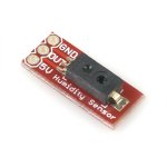
Has anyone any experience of this humidity detector. Forum search revaled nothing.

I was given one, along with a Speakjet I.C. and a Sumo 14D by
my Sis in law visiting from the states. Better that duty free fags !!

Had a quick skim of the data sheet. Seems fairly straighforward but two things jumped out at me - Minimum load 80K and a bit of maths will be needed, Output / RH graph looks a bit Y=MX+C ish. Any experiences will be appreciated.

Russ
 

Attachments

Last edited:

russbow

Senior Member
I'm getting in a total mess with this!

I hooked up the HIH 4030 with a 100K load resistor connected to my DVM.

I was pleased that the voltage output from the HRH matched the RH values on the datasheet graph when compared with another sure module. I.E. if the sure module indicated 40% RH, then datasheet for the HRH 4030 suggested 2.0 volts. It did exremely closely, and it held good across a wide range.

I took a good number of measurements and graphed the results.

From the straight line equation Y=MX+C I calculated the slope M to be 0.03, and the intersection C to be 0.78. Again these checked out across the ranges measured

So, from this Volts = (.03 x RH) +0.78 EQUATION 1

Now looking at adc on the 08m. I connected a 10k pot across 5.0 volts, connected adc 4 of the 08m to the wiper and measured from here to 0 volts with the DVM.. Advancing the input from zero to 5.0 volts in 100mV steps I got an extremely linear count from 0 to 1024

From this straight line, the intersection C was zero and the slope M was 0.0048

Re-arranging Y (volts) = M (slope) x X (adc) +C, I get, as C=0,

Volts = ADC x 0.0048 EQUATION 2


Putting this into EQUATION 1, I get

RH = [(ADC x .0048) - 0.78] /0.03

Looks good to me and works on paper. Don't know how to get the picaxe to do it !!

Totally lost

R.
 

Dippy

Moderator
Confusing.

What value of RH do you get if the ADC value is, for example, 10 ?

PS. Why didn't you just stick the sensor onto ADC and do a direct ADC vs RH graph ?

Generally:
Well, don't forget that *0.00488 = /~204.9 ..... and dividing by 0.03 = x 33.3
With integer stuff it's often better to think in vulgar fractions than decimal places.
With 10 bits of ADC you have plenty of space for multiplying to 'work out' some of the decimal places.
i.e. timesing things up first before division.
 
Last edited:

russbow

Senior Member
The final equation RH = [(ADC x .0048) - 0.78] /0.03 holds good.

Working it out for all ADCs between 0.5 volts and 3.5 volts gives me an RH value that matches the volts / Rh graph in the datasheet.

See what you mean by vulgar fractions. Could be approximated to

[(ADC/208)-1] x 33.

I'll run this through the calculator for the range and see how close results are.

PS. Why didn't you just stick the sensor onto ADC and do a direct ADC vs RH graph ?
Did originally, but didn't have a RH yardstick to make sense of it.

Now got three columns of figures - Volts, ADC & RH but still ends up with the dreaded decimal maths.

R.
 

hippy

Technical Support
Staff member
The final equation RH = [(ADC x .0048) - 0.78] /0.03 holds good.
If that's what you want then ...

RH = [ (ADC x .0048) - 0.78 ] / 0.03
RH = [ (ADC x 48) - 7800 ] / 300
RH = [ (ADC x 24) - 3900 ] / 150

RH = [ (ADC x 12) - 1950 ] / 75

or

RH = [ (ADC x 12) / 75 ] - 26
 

russbow

Senior Member
That's absolutely amazing - thank you.

I follow your process throughout but would never have got there myself. Appreciate your help.

R.
 

russbow

Senior Member
So far so good

Stuck on the last step !!

According to the chip datasheet, not only is the chip sensitive to light - no problem, but need a bit of maths to compensate for temperature.

In spite of understanding the previous process, where do I start with this?

True RH = RH / (1.0546 – 0.00216T), where T in ºC

RH and T are always whole numbers

Something like 10546 - 21*T / 10000

This loses the 6 before the T which could be quite significant. Can't scale up a further 10 as get 105460 which is too big.

And I did maths long before you could buy a calculator !!!!!

R.
 

fernando_g

Senior Member
I've succesfully used the HIH-4000 for a temperature/humidity logging device with a 18X.
Its first order transfer function and temp comp are identical to your device.

To perform the required maths, I went to prof's Anderson's website:

www.phanderson.com

He has an EXCELLENT tutorial on how to do exactly what you require. For my project, I copied the subroutine from his website and coded everything else around it.

Prof. Anderson also browses this forum from time to time.
 
Last edited:

russbow

Senior Member
Thank you Fernando for that link. A good tutorial as you say, and a working example. I can see how the above maths was approached, would never have thought of a high word and a low word.

What are you using as the load resistor on your sensor. Page 7 of the datasheet suggests > 80K. Is this compatable with ADC.

I ask because as a bench mark I am using a Sure module, already compensated and outputting in ascii. This routine is a consistent 6% above the the Sure figures.

In fact my own routine tracked the Sure reading well, but progressivly lower below about 60% and progressivly higher above 60%, indicating my slope measurement is out. These results were without temperature compensation, hence the need to now play with these figures.

Of course, one cannot be sure that the SURE module is accurate.

Russ
 

fernando_g

Senior Member
What the data sheet is saying (for the minimum load requirement) is that the device will be accurate with a load that sould not be lower than 80K, that the device likes to see a high impedance. As such, I connected the sensor's output directly to the PICAXE's analog input. The input is load enough.

Although this seems to be working correctly, I have not had the opportunity to calibrate it against a known standard. My concern (which I don't know if it should be a concern or not) is whether the PICAXE's input (which likes to see a low source impedance) may be loading the sensor during the critical sampling period.
 

russbow

Senior Member
Thank you all for your inputs. Got there at last. Phil Anderson's routine is perfect. Interesting that my "home brew" results followed P.A.s very closely which was also progressivly higher and lower than the Sure module. So I wasn't far off course.

Now for the final bit. How do I mount this ( attached JPG )? I plan to put all the workings in a sealed box some 20 feet up the mast. Guess the sensor must be open to the air, but kept dry. Some water repellant gauze cover ? Can't really put a Stephenson Screen up there.

Open to all ideas!

Russ
 

Attachments

fernando_g

Senior Member
What I did was to take a completely sealed enclosure, and drill a couple of 5mm holes on the side facing downwards. And my PWB layout was such that the temp and humidity sensors aligned with the holes.
 
Top