"not for automotive use" is kinda a general statement.
I think it's an issue of how "automotive use" is defined.
For me it means anything which connects to the vehicle power supply, signals or control lines or any controller within a vehicle, directly or indirectly, or to any mechanical mechanism of that vehicle. If it doesn't do any of that, is self-contained, even if used within a vehicle it's not "automotive use".
Where there's an interface to a vehicle that interface has a risk of failure, and that failure has a risk of greater consequences, and those consequences can be life threatening, hence the entire chain backwards is safety critical including the PICAXE and its circuit.
As PICAXE is not recommended for use in safety critical applications, "not for automotive use" logically follows.
Anyone who has worked on any software for long enough will recognise the potential for unexpected software bugs, realise that not all possibilities can or have been tested, that some peculiar combination of factors can cause a software system to catastrophically fail or behave in unexpected ways. Just because software doesn't fail in a billion uses doesn't mean there isn't a bug there waiting to bite. How many times have we seen buggy PICAXE code such as ...
ReadAdc10 1, w0
If w0 > 512 Then ...
If w0 < 512 Then ...
There's less than a one in a thousand chance of that failing. Add another similar bug and it could be one in a million chance of failure, and sod law's may make that even less likely in reality, but the bug really is there. When such bugs are revealed it often seems in hindsight incredible that they were missed and that they had such low impact.
Even if it were possible to ensure safety critical compliance with regards to hardware, that's almost impossible to do for software and certainly so for home and hobbyist programmers. Even if a programmer could guarantee their code we do not guarantee that for our firmware nor do Microchip guarantee their silicon.
Any software that affects a vehicle could affect it adversely, and that safety critical chain is again established, and "not for automotive use" kicks-in again.
in general, i am still searching for examples of where/why picaxe failed in automotive use. please supply any links to any info or post here so i can read up on it. thnx.
I don't think there will be many examples as automotive use is discouraged. There have been posts where people have done automotive projects and report 'no problems', though that should really be 'no problems, so far'. One can never tell if it's by luck or design that it has seemingly worked, whether it is actually okay or on the edge of failing, whether what they have is specific to their vehicle, that what works one day will work the next. That someone played Russian Roulette and lived to tell the tale doesn't mean all will.
I think there have been a few reports of failure issues in automotive use though I cannot point to them. I recall one was related to supply using a standard 7805 regulator.
the Toyota ECM with all of its controls is probably 1000x more complicated than any simple picaxe circuit. i take a wild guess and say the Toyota issue of "SUA" is sensationalized driver error.
It is possible, it's also possible that there is a fault which others are seizing upon which isn't actually to blame in their own circumstances.
I had a six month old car, driving at fairly high speed I had to brake quite hard and the car leapt into the lane of oncoming traffic. To most of the world it probably looked like driver error, failure to leave braking space and having to steer round the vehicle in front to avoid crashing into it, driver error-come-panic in doing that rather than crashing in-lane. Turned out to be the brake calliper sometimes seizing on one side.
It's easy to jump to conclusions, often wrong ones. I'd have assumed driver error as an outside observer of my incident, I don't think my passengers truly believed it was a, previously unseen, intermittent vehicle fault at the time. Even I wasn't sure what had happened at the time, couldn't definitely say it wasn't a subconscious knee-jerk response, though didn't believe it was. One second I was in this lane, the next in the wrong one. Thankfully I steered out of trouble.
I was perhaps lucky that the engineers did investigate and report honestly, not come back with 'nothing wrong, mate'. If they had and some systemic problem did later emerge I'd reflect back on that possibly having been the cause, but no one would ever really know if it was or wasn't, incredibly difficult to prove either way.
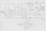
 228.6 KB Views: 299
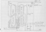