westaust55
Moderator
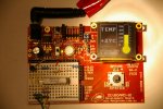
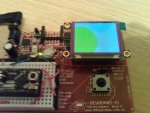
I did some first time testing with some 4D Systems OLED displays last night.
Contrary to other posts earlier this year on this forum, I found that they come with this firmware installed and capable of serial comms as supplied.
My initial tests found that the timing of initial delays (PAUSE command) was marginally critical. Too short and the OLED display is not ready, too long and the OLDE display switches to splash screen display mode (with the standard 4D Systems details scrolling – unless you have changed this).
These displays have both Rx and Tx pins so one could monitor the OLED display for a response to know when the current command is complete. However, I did some testing based upon use of PAUSE commands in a 1-wire comms mode as used by many PICAXE users.
A couple of simple programs written last night using a PICAXE 08M as the host to drive the OLED displays. I use the HIGH 4 to set the PICAXE serial output high as soon as possible as the OLED module datasheets indicate a low state 100ms after OLED module power up may be seen as the start of auto baudrate detection.
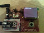
This first code clears the display and uses the command ($54) to print single ASCII characters ion the display and finally sets the background colour to black.
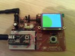
This program is much the same as the first but uses the command ($53) the print a string of ASCII characters to the display. The OLED can accept ASCII characters strings up to 255 characters in length
I found that the various OLED display sizes can be optimised with differing minimum delay durations after commands to the screen. This is seemingly is due to two aspects:
1. the screen pixel count (obvious) and
2. possibly the onboard processor speed or overheads (less obvious).
The attached table gives my indication of the delays required dependant upon the command and where necessary the baud rate.
As and when time permits I may add to these details.
Trust others find this information of use.
Contrary to other posts earlier this year on this forum, I found that they come with this firmware installed and capable of serial comms as supplied.
My initial tests found that the timing of initial delays (PAUSE command) was marginally critical. Too short and the OLED display is not ready, too long and the OLDE display switches to splash screen display mode (with the standard 4D Systems details scrolling – unless you have changed this).
These displays have both Rx and Tx pins so one could monitor the OLED display for a response to know when the current command is complete. However, I did some testing based upon use of PAUSE commands in a 1-wire comms mode as used by many PICAXE users.
A couple of simple programs written last night using a PICAXE 08M as the host to drive the OLED displays. I use the HIGH 4 to set the PICAXE serial output high as soon as possible as the OLED module datasheets indicate a low state 100ms after OLED module power up may be seen as the start of auto baudrate detection.
This first code clears the display and uses the command ($54) to print single ASCII characters ion the display and finally sets the background colour to black.
Code:
#PICAXE 08M

HIGH 4							; set pin 4 high to prevent false auto baud detection
PAUSE 1000						; wait at least 1000ms for OLED display to internally initialise

SEROUT 4, T2400, ($55)				; automatic baud rate detection bit stream
PAUSE 10

SEROUT 4, T2400, ($45)  				; clear the screen
PAUSE 10						        ; uOLED-96-G1/128-G1 = 10ms; 160-G1 = 20/30/40ms

SEROUT 4, T2400, ($42, $DF, $E0)  		; set the background to light yellow
; setting the background colour involves time to colour each pixel varies depending on screen size
PAUSE 350						        ; uOLED-96-G1 = 350ms; 128-G1 = 1000ms; 160-G1 = 1800

SEROUT 4, T2400, ($54,"W", $00, $00, $FF, $FF) 	; letter W at col-row position 0,0 in white
;PAUSE 10
SEROUT 4, T2400, ($54,"R", $02, $00, $F8, $00) 	; letter R at col-row position 2,0 in red
;PAUSE 10
SEROUT 4, T2400, ($54,"G", $03, $02, $07, $E0) 	; letter G at col-row position 3,2 in green
;PAUSE 10
SEROUT 4, T2400, ($54,"B", $04, $03, $00, $1F) 	; letter B at col-row position 4,3 in blue

PAUSE 1000
SEROUT 4, T2400, ($42, $00, 00)  				; set the background to black

DO
LOOP
This program is much the same as the first but uses the command ($53) the print a string of ASCII characters to the display. The OLED can accept ASCII characters strings up to 255 characters in length
Code:
#PICAXE 08M

HIGH 4							; set pin 4 high to prevent false auto baud detection
PAUSE 1000						; wait at least 1000ms for OLED display to internally initialise

SEROUT 4, T2400, ($55)					; automatic baud rate detection bit stream
PAUSE 10

SEROUT 4, T2400, ($45)  					; clear the screen
PAUSE 40						; uOLED-96-G1/128-G1 = 10ms; 160-G1 = 20/30/40ms

SEROUT 4, T2400, ($42, $00, $E0)  			             ; set the background colour to dark green
; setting the background colour involves time to colour each pixel varies depending on screen size
PAUSE 1800						; uOLED-96-G1 = 350ms; 128-G1 = 1000ms; 160-G1 = 1800

SEROUT 4, T2400, ($53, $08, $20, $00, $1F, $00, $02, $01, "01234567890123456789012345678901234567890123456789", $00)
PAUSE 75
SEROUT 4, T2400, ($53, $38, $40, $00, $F1, $00, $02, $02, "XYZ", $00)
PAUSE 1000
SEROUT 4, T2400, ($42, $00, 00)  			              ; set the background to black

DO
LOOP1. the screen pixel count (obvious) and
2. possibly the onboard processor speed or overheads (less obvious).
The attached table gives my indication of the delays required dependant upon the command and where necessary the baud rate.
As and when time permits I may add to these details.
Trust others find this information of use.
Attachments
-
27.8 KB Views: 90
Last edited:
")