Making best used of ADC resolution for reading battery voltage

axeman22

Member
Hi,

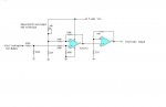
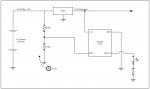
trying to make a PICAXE circuit which does a few things(not shown) but also monitors the battery voltage by way of taking a reading on the ADC0 input. The voltage divider network I have seems ok. The 14M has 1024 bits of ADC so resolution should be good. From my readingthe voltage on the ADC cannot exceed Vcc for the Picaxe chip so max voltage ever presented no higher than 5V. With the divider network I have 13Volts at the battery should present 5 volts at ADC0. given that the batery will nevr be below 10Volts unless it's dead I would like to make a circuit which gives me the ability to do an offset zero voltage reading. i.e zero Volts at ADC0 input equals 10 Volts battery boltage and 5 Volts ADC0 input equals 13 volts battery voltage. This way I can make maximum usage of the ADC resolution in the practical measuring range required.

all things being equal I plan to make the LED flash in accodance with the battery voltage reading - i.e. display battery voltage in morse code or similar.

appreciate all ideas!

Thanks,

Ian
 

Attachments

hippy

Ex-Staff (retired)
Welcome to the PICAXE forum.

What you need to do should be possible using an op-amp; subtract the 10V, leaving 0V..3V, then set the op-amp gain to <whatever> so it multiplies up to 0V..5V. Probably best to give it a bit of headroom either way.

Or divide down to below 5V first, then apply the op-amp; probably easier if using a 5V supply.

Added : Your circuit shows a 7905 regulator; that's a -5V regulator. You probably want 7805. Though I think there's going to need to be some clarification on the polarity of your voltages anyway; -12V into regulator.
 
Last edited:

MartinM57

Moderator
A few comments:
- you need to use lower value resistors in the potential divider - more like 16K/10K - to be inside the spec of the allowed input impedance to a PICAXE ADC input
- you could achieve what you want with an op-amp based circuit before the ADC input but you'll probably need a -ve voltage supply (Google "op-amp differential amplifier" and come back and ask any questions)
- ADC readings are referenced to the PICAXE power supply, so you get amazing resolution (1024 different values) but unidentified accuracy. If you're common-or-garden 7805 is giving out 5.1volts then you're guaranteed to be 2% out already if your assuming that an ADC reading of 1023 == 5 volts.

...so the bottom line is do you really need all that accuracy?

I'd start the other way round - choose an accuracy (maybe 2% is good enough) and then redo the sums. I expect you'll find the 12 bit ADC resolution and a simple potential divider, like what you have, will be fine.
 

axeman22

Member
Thanks Gents,

yes my voltages all wrong.. everything is +ve and should be a +ve reg also so yes 7805.! :)

I have done a reasonable amount of playing with OpAms.. suffice ot say I think I get it,though the big concern I would have there is current draw. I want to keep current draw right down to an absolute minumum. This is actually for a solar powered GeoCache that will flash led sequences at night time based on LDR sense. I'm going to put the PICAXE into sleep mode and hae that control everything else via a FET and output pin. So on the 12v Sense side I used high value resistors to lower the current right down to bugger all.


you need to use lower value resistors in the potential divider - more like 16K/10K - to be inside the spec of the allowed input impedance to a PICAXE ADC input
- you know, I just don't get that part.. could you explain. I have done electronic theory but this is one part that never sank in so well.

you could achieve what you want with an op-amp based circuit before the ADC input but you'll probably need a -ve voltage supply (Google "op-amp differential amplifier" and come back and ask any questions)
- Se my comments above.. power consumption and simplicity I think would lead me away from the op amp path. Designing this circuit is to me as much about the challenge of making something which is simple, functional and sticks within the power budget!


ADC readings are referenced to the PICAXE power supply, so you get amazing resolution (1024 different values) but unidentified accuracy. If you're common-or-garden 7805 is giving out 5.1volts then you're guaranteed to be 2% out already if your assuming that an ADC reading of 1023 == 5 volts.
- Good point.. really, if I can get two digit resolution that's fine.. I just want to be able to make it tell me that the battery voltage of the 12V cell is 12.41Volts etc.. should be plenty for that. and yes accuracy really is no BIG deal, just an ideal.

great input.. thanks for prompt replies!
 

Dippy

Moderator
Good points on volts supply/reference.

Note that with a bit of hunting around you can get some pretty high-spec regulators.
Some will have a low-ish output current limit.

Example:
LPC2950.
This is available as LPC2950-C50 or LPC2950-AC50 . The latter (with an 'A') is more accurate/precise with a slightly better tempco.

However, I really think that unless you do a bit of 'extra work' you will be pushing it to get accuracy to 2 decimal places. Is it really necessary?

P.S. For precise/reliable ADC-ing it is crucial to have good decoupling dor the PICAXE power pins, as close as physically possible to the chip pins.

I've never tried it with PICAXE, but is there a POKE so that you can connect a pukka voltage reference to the appropriate pins?
 
Last edited:

vttom

Senior Member
Instead of a resistive voltage divider, you could use a Zener diode to "subtract" out ~10V. That'll give you a 3v swing into the ADC which will give you 3/5 of the 1024 value range. That works out to ~5mV per ADC unit, e.g. (3/5)*1024 = 614; 614 * 0.005V ~= 3V.
 

MartinM57

Moderator
you need to use lower value resistors in the potential divider - more like 16K/10K - to be inside the spec of the allowed input impedance to a PICAXE ADC input
- you know, I just don't get that part.. could you explain. I have done electronic theory but this is one part that never sank in so well.
Simple(ish) answer:
a) max source impedance is given as 10K in the PIC datasheets
b) the source impedance is the impedance (= resistance if your talking strict DC) looking out of the ADC back into the circuit that is connected to it. You have 10M to earth and 16M to Vbattery. The impedance of this can be worked out by determining the Thevenin equivalent circuit for these two resistors and the battery (see for example http://hyperphysics.phy-astr.gsu.edu/Hbase/electric/thevenin.html). So you have 10M in parallel with 16M, which is 6.15Mohms - slightly above 10kohms :D With the 16K and 10K I suggested, you have 6.15Kohms

Complex answer:
a) max source impedance is given as 10K in the PIC datasheets
b) the source impedance you have is....6.15Mohms
c) with an impedance greater than that recommended, the capacitor inside the ADC circuitry of the PIC can't charge up to the external voltage value during the ADC conversion time period inside the the PIC. Even though you have only DC at the ADC pin, the internal capacitor has to charge up from 0v as it is discharged (so says the PIC18F1XK22/PICAXE 20-X2 datasheet) after every ADC conversion. If it doesn't charge up enough, you will get an an invalid reading

So an interesting experiment (I've never done it) is to try it with 16M and 10M as your potential divider and see what:
- your multimeter reads on the ADC pin
- the ADC reading gives
..and then try it with 16K and 10K, and see if there is any difference.

If there isn't, then you may get away with the high value resistors to minimise leakage. If there is (and you want 2% accuracy, so hardly any difference will be unacceptable), then you will need to lower the resistors and think again how to minimise leakage from the battery...
 

MartinM57

Moderator
Instead of a resistive voltage divider, you could use a Zener diode to "subtract" out ~10V. That'll give you a 3v swing into the ADC which will give you 3/5 of the 1024 value range. That works out to ~5mV per ADC unit, e.g. (3/5)*1024 = 614; 614 * 0.005V ~= 3V.
'fraid not. An in-series zener diode (pointy end direct to the battery, blunt end directly to the ADC) needs a current flow through (5mA ballpark?) it to have its designed voltage appear across it. With it connected directly to the ADC input (very high impedance), this current can't flow so it doesn't work.

I just proved it myself (after a fashion):
- SLA battery, measures as 12.91v (-ve to +ve termianls) with multimeter
- 5.1v zener in series, measures as 11.01v (-ve terminal to blunt end)
..so the ADC will see 11.01v.

Fail :(
 

Dippy

Moderator
Agreed.
A zener is totally unsuitable.
As Martin has just shown a zener's Zener Voltage varies with current; also temeperature.
People's misunderstandings of zeners is very common.
If you start using Zeners then you can forget accuracy.

If you want precision then you are back to op-amps top quality components and super-dooper regulators/references.
Or use a higher bit resolution ADC - with all the care that requires too.

Do you REALLY need 2 decimal places of accuracy/precision?
I would have thought that it's overkill for your average battery charger.
 

BeanieBots

Moderator
just to emphasise a few points already made.
Absolutley NO to the zener idea for the reasons given.
For even low resolution ADC work, keep zeners out of the equation even when used as over-volt clamps. They're simply just too slopy.

Op-amp(s) configured as a differential input against a reference is the only way you will get 2 decimals from a nom 12v source.

A 'standard' 7805 regulator will have a significant temp coef if it's a cheapie. Have a careful read of your regulators datasheet to see if it fits within your required accuracy spec when using it as a reference. Don't forget, it will be the reference for both your ADC reading AND your op-amp offset.

Also, a 'standard' 7805 regulator will pull about 4-5mA quiescent current so there is no point using a very high impedance divider and compromising your reading even further.
By using op-amps, you can have a high impedance on the battery and a low impedance to the ADC input. A quad op-amp such as the 'good old' LM324 only draws about 1mA quiescent.

Finally, 0.01v accuracy on a Pb battery is a little meaningless unless you are also taking temperature compensation into account.

If you REALLY want a finely trimmed trip point and don't want to take the op-amp route, then add a trim pot into the middle of your divider and use that to trim the precise ADC trip point. (but keep the total impedance below 10k)
 

sghioto

Senior Member
axeman22,

If you do decide to go the opamp route here's a "difference" amp schematic and with the values shown is very close to the 0 to 5 volt output required. Would not recommend a LM324 because with a 5 volt supply a rail to rail output type is required. Total current drain is below 3 ma with a 10 to 13 volt input.

Steve G
 

Attachments

fernando_g

Senior Member
There is a trick that I sometimes use, when employing the ADC conversion.

As previous posters have indicated, the PICAXE uses its own supply voltage as the ADC reference. Therefore it makes sense to use an adjustable voltage regulator to trim the voltage to an exact known value.

And if you are going to adjust the voltage, adjust it to 5.12 volts.
That way each bit in an ADC10 conversion equals to exactly 5 mV, a nice round number...........
 
Last edited:

axeman22

Member
Thanks all replies...

In all honesty..;

- perhaps I don't NEED 2 decimals of accuracy however this is about the challenge and fun as much as anything so if it can be done easily enough and keeping things simple then I'd like to aim for it.

- I really appreciate all input, some great ideas here that I hadn't thought about. I love that I can make a post here and get such great feedback - thanks.

- very interesting re the zener's.. I also didn't think they were that accurate.

I can put a PICAXE into sleep mode which draws about 350uA of current.. perhaps I could do the voltage checking only when the PICAXE is alive and actively running a prog command other than sleep. I was thinking of using a FET of some sorts as a low power switch. I could take an output pin and effectively enable the voltage divider circuit with the FET - this would mean it uses zero current aside from when sampling routines are occurring and the FET is hard on.

- if anyone feel like adding a FET into the voltage circuit as a switch with the gate tied to a PICAXE output love to see that.

- I'm not that volrage reg boffed up, if anyone has a great v/reg with high accuracy and low quiescent current draw which is still reasonably cheap please list it here..

Thanks!
 

Dippy

Moderator
"I'm not that volrage reg boffed up, if anyone has a great v/reg with high accuracy and low quiescent current draw which is still reasonably cheap please list it here.."

- I have already done so yesterday... have a look.
Also add the LM2936 - not so good as the other one I mentioned.
In any event, your device needs calibration and a frig factor included in your code calcs.
There are others, but you could get started with these.
Get the Data Sheets and have a good read.

FET switch shouldn't pose a problem for simple DC circuits.
Just make sure that:
A) The FET Rds-on is 'insignificant' compared to your network resistance - no problem theoretically.
B) The FET gate can't float - no problem.

You won't need super-dooper accuracy for your prject I'm certain. But I can assure you that the 'fun' aspet will disappear if you start struggling for hundredths :) And you WILL struggle if all this is new to you. No such thing as magic.

I would suggest you get the basics working before complicating it any more.
I reckon you have enough answers to dig out the bread board and give it a go now.
 
Last edited:

axeman22

Member
thanks! - whilst on the subject of FET's.. I have done some toolin about and think I have them a bit worked out but I have a question that I'd really appreciate an answer on.

The FET I played with was effectively a short circuit, and when you apply voltage to the gate it pinches off. Is there a FET which is open circuit from Source to Drain and is short circuit only when you apply voltage to the gate, to switch it on..?

also, in simple terms what is the different between P and N channel.. I have the feeling this is not the answer to my question above.

being a bit lazy here.. but really appreciate the help.!
 

Dippy

Moderator
Well, I don't know how you connected your FET, but have a look at some FET tutorials on the web. What you've done sounds wrong.

When connected correctly the FET will conduct when the Vgs is adjusted as per spec in data Sheets.
So, you can use a N chan as a low sided switch and a P chan as a high sided switch - in a similar way to NPN and PNP trannies respectively.

Do another hours worth of toolin around on the internet for some examples, I haven't time to draw anything out sadly. And I've retired from MOSFETs.

Read those tutorials. Then you will see the diff between P and N channel.
A FET/MOSFET can NOT always be considered as a solid-state relay. So many people make this incorrect assumption.
 

fernando_g

Senior Member
The FET I played with was effectively a short circuit, and when you apply voltage to the gate it pinches off. Is there a FET which is open circuit from Source to Drain and is short circuit only when you apply voltage to the gate, to switch it on..? QUOTE]
Most likely you have used a JFET which is a depletion-mode device, versus a MOSFET, which is an enhancement-mode device (well at least the overwhelming majority of discrete MOSFETS are enhancement).

Esentially, a depletion mode device is always on and you have to deplete the channel with the application of a gate field to turn it off.

An enhancement mode, on the other hand, is always off, and you have to enrich the channel to allow conduction.

Additionally, there are N and P channels... So you have got 4 different devices to play with.

As Dippy says; read some web tutorials or take any basic electronics book, they will explain in detail the different operating modes.
 
Top