My version of Magic Switchboard

WayneT

Member
I had an extra PicAxe-18X after doing a recent project for a coin display for my arcade machine, since I didn't blow up the first chip.

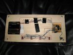
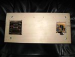
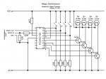
I decided to build the Magic Switchboard (Magic SwitchBox) using the spare chip and after taking the code that Technical put up in another thread, and making some substantial changes, I'm now ready to post photos, schematics and code and explain some of the changes.

I changed the input and output pins required in the code so it would be easier to wire the circuit. The inputs are 1, 0, 7, 6 (in that order for switches 1-4). The outputs are 7, 6, 5, 4 (in that order for lights 1-4).

I also added a tweak that allows the timeout to function even if all switches have not been learned. This allows it to reset itself if an audience member flips a switch out of sequence (which has already happened to me!). I just explain that the person just doesn't have the magic and then just flip the switch off to let it reset.

I've added a multi-bulb/direction feature. If switch-1 is the last turned off, it acts like it normally did before, bulb-1 thru bulb-4 in sequence. If switch 2, 3 or 4 is turned off last, it will start in that position instead. Odd bulb starts will sequence left to right. Even bulb starts will sequence right to left. This means if I turn switch 2 off last, the next reset will be in the order of 2,1,4,3. If switch 3 is switched off last the next order will be 3,4,1,2. If the 4th switch is turned off last, the order will be 4,3,2,1.

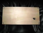
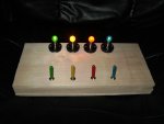
The woodworking still needs work - I need to clean up the sides (sand them smooth) and try to find some 2 inch wide veneer edging tape to apply to the sides (to cover the seams of the multiple layers of wood). Then I will sand the corners smooth and stain the board, finally applying a urethane coating.

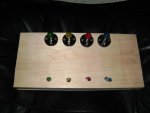
The switch caps are 1 inch sections of quarter-inch dowel that I rounded on one end, and drilled a hole in the other end. I painted the bulbs and the switch caps with the same glass stain, which I bought at a local craft store. The stain is intended for "Stained Glass Suncatchers".
 
Last edited:

westaust55

Moderator
Sounds an interesting modified project.

Await your further information (pics and code etc)
 
Last edited:

WayneT

Member
The wood is actually four layers. The top piece with the switches and lamp holders attached is a quarter inch piece of aspen. The dimensions of each piece is 5.5" x 12" The second piece is half inch aspen and it has tracks for the wiring, the switches, battery pack and circuit board. The third piece is also half inch aspen and has the openings for the battery pack and circuit board. This piece covers the wiring tracks. The last piece is the cover and it is made of quarter inch aspen. It has a hole cut in it to gain access to the power switch.

The circuit board was a perf-board with solder pads (sold by Radio Shack). I laid solid wire in place across the pads and flooded with solder to run the traces, but unfortunately I didn't get any pictures of the back. All hookups are made with machined socket pins. There is a 2-pin power connector for +6v and ground. There is a 4-pin connector for the lamp wiring and a 4-pin connector for the switch wiring. There is a 2-pin connector with +6V on each pin, one is used for the lamps and the other for the switches. All of the wiring is stripped and solder tinned ribbon cable since the wire size is perfect to insert into machined sockets, once the wire is stiffened with solder.

Instead of using a ULN2803A Darlington driver chip, I used four 2N2222 NPN transistors to drive the lamps. The emitters are tied to ground (0V) so they are 0V switches and the lamps require +6V to light.
 

Attachments

Last edited:

WayneT

Member
The last attachments are with the lights lit, showing a better angle of the switch caps, and then the schematic. For programming the circuit, I used my "trademarked" 5-pin header. Actually it's half of the header I used on my coin display, consisting of pins 1-5 of the serial cable on one half of a 10-pin ribbon-cable connector. The coin display I previously made had an unused second row of header pins - which keeps from attaching the connector incorrectly. The code is:

Code:
#picaxe 18x
 

' Magic Switchboard - original source by "Technical" from PicAxe Forum
'                     Modified for PicAxe 18x by Wayne Thomason of Addison, TX USA
'
'                      mods: different inputs and outputs from original (easier to wire circuit)
'                            timeout functions even without learning all 4 switches
'                            starting point and sequence direction dependent on last switch turned off
'
' Assumptions
' 1. Times out after 10 seconds of all switches in the off position
'    regardless of whether all switches are learned yet
' 2. All switches must be off at start
' 3. All 4 switches must be switched on before that sequence is learned
' 4. bulbs/LEDs on outputs 7, 6, 5 & 4
' 5. switches on inputs 1, 0, 7 and 6
' 6. first pattern is left to right, bulbs 1, 2, 3, 4  (outputs 7,6,5,4)
' 7. subsequent patterns are determined by last SWITCH turned off:
'       Switch 1 = 1234 order (bulb 1 first, then right in sequence)
'       Switch 2 = 2143 order (bulb 2 first, then left in sequence, wrapping after first)
'       Switch 3 = 3412 order (bulb 3 first, then right in sequence, wrapping after last)
'       Switch 4 = 4321 order (bulb 4 first, then left in sequence)
 
symbol flags = b0  ' flags to remember whether a switch has been learnt yet
symbol flag0 = bit0
symbol flag1 = bit1
symbol flag2 = bit2
symbol flag3 = bit3
 
symbol light0 = b1 ' variable to remember which switch is which light
symbol light1 = b2
symbol light2 = b3
symbol light3 = b4
symbol starting_lite = b6 ' variable to set starting light position (and direction)
 
symbol position = b5  ' position counter
 
symbol timeout_counter = w6 ' timeout counter
symbol timeout = 500    ' timeout set to 10s = 10 000ms = 1000 x 10ms

'Change to smaller number when simulating or you will get bored!
 
starting_lite = 1

' Start of program
do_reset:
'                ' reset position counter       
 if starting_lite = 1 then  ' if starting with bulb 1, position reset to 15.
    position = 15 
 end if
 
 if starting_lite = 2 then  ' if starting with bulb 2, position reset to 14.
    position = 14
 end if
 
 if starting_lite = 3 then  ' if starting with bulb 3, position reset to 13.
    position = 13
 end if
 
 if starting_lite = 4 then  ' if starting wtih bulb 4, position reset to 12.
    position = 12
 end if
 
 flags = 0  ' reset flags
 light0=0   ' reset all lights to off.
 light1=0
 light2=0
 light3=0
 
' Learning loop
waiting_to_learn_loop:
' if not learnt switch learn it
 if pin1 = 1 and flag0 = 0 then learn0
 if pin0 = 1 and flag1 = 0 then learn1
 if pin7 = 1 and flag2 = 0 then learn2
 if pin6 = 1 and flag3 = 0 then learn3
 
 ' we have learnt that switch so light output accordingly
 if flag0 = 1 then
  if pin1 = 1 then
   high light0
  else
   low light0
  end if
 end if 
 if flag1 = 1 then
  if pin0 = 1 then
   high light1
  else
   low light1
  end if
 end if 
 
 if flag2 = 1 then
  if pin7 = 1 then
   high light2
  else
   low light2
  end if
 end if 
 
 if flag3 = 1 then
  if pin6 = 1 then
   high light3
  else
   low light3
  end if
 end if
 
 if pin0=0 and pin1=0 and pin7=0 and pin6=0 then    ' count down to timeout even while in learning loop
    pause 10   'wait 10ms
    inc timeout_counter  'inc timeout
    if timeout_counter > timeout then 
       timeout_counter=0
       goto do_reset
    end if
 else
    timeout_counter=0
 end if
 	
 goto waiting_to_learn_loop
 
' Learn a light position and set flag so we know that switch is done
learn0:
 ' position gives you the output for this switch
 flag0 = 1    ' set flag
 light0 = position   ' remember position for this switch
 goto learn_end
 
learn1:
 ' position gives you the output for this switch
 flag1 = 1    ' set flag
 light1 = position   ' remember position for this switch
 goto learn_end
 
learn2:
 ' position gives you the output for this switch
 flag2 = 1    ' set flag
 light2 = position   ' remember position for this switch
 goto learn_end
 
learn3:
 ' position gives you the output for this switch
 flag3 = 1    ' set flag
 light3 = position   ' remember position for this switch
 'goto learn_end
 
learn_end:
if starting_lite = 1 then                    ' if starting with bulb 1
   dec position                              ' subtract 1 to position counter
   if position < 12 then have_learnt_all     ' all done
end if

if starting_lite = 2 then                    ' if starting with bulb 2
   inc position                              ' add 1 to position counter
   if position > 15 then                     ' if position counter is greater than 15 
      position = 12                          ' make it 12 instead (loop around to bulb 4)
   else 
      if position = 14 then have_learnt_all  ' else if position equals 14 then all bulbs learned
   end if
end if

if starting_lite = 3 then                    ' if starting with bulb 3
   dec position                              ' subtract 1 from position counter
   if position < 12 then                     ' if position counter is less than 12
      position = 15                          ' make it 15 instead (loop around to bulb 1)
   else
      if position = 13 then have_learnt_all  ' else if position equals 13 then all bulbs learned
   end if
end if

if starting_lite = 4 then                    ' if starting with bulb 4
   inc position                              ' add 1 to position counter
   if position > 15 then have_learnt_all     ' all done
end if
  
    
 goto waiting_to_learn_loop   ' not all done so back to loop
 
' now simply loop reacting to the switches
' timeout_counter value will increment every 10ms
' however if any light is on the timeout_counter is reset
' so this means the timeout will only 
' occur after 10 secoonds of all switches off
 
have_learnt_all:
 if pin1 = 1 then
  high light0
  timeout_counter = 0
 else
  low light0
 end if
 
 if pin0 = 1 then
  high light1
  timeout_counter = 0
 else
  low light1
 end if
 
 if pin7 = 1 then
  high light2
  timeout_counter = 0
 else
  low light2
 end if
 
 if pin6 = 1 then
  high light3
  timeout_counter = 0
 else
  low light3
 end if
 
 
 'Set which bulb will start next round. (only if switches all learned)
 if b0 = 15 and pin1=1 and pin0=0 and pin7=0 and pin6=0 then  ' if switch 1 on alone, set bulb 1 first
   starting_lite=1
 end if
 
 if b0 = 15 and pin1=0 and pin0=1 and pin7=0 and pin6=0 then  ' if switch 2 on alone, set bulb 2 first
   starting_lite=2
 end if
 
 if b0 = 15 and pin1=0 and pin0=0 and pin7=1 and pin6=0 then  ' if switch 3 on alone, set bulb 3 first
   starting_lite=3
 end if
 
 if b0 = 15 and pin1=0 and pin0=0 and pin7=0 and pin6=1 then  ' if switch 4 on alone, set bulb 4 first
   starting_lite=4
 end if
 
 pause 10   ' wait 10ms
 inc timeout_counter ' inc timeout
 
  	' if timed out then reset else loop
 if timeout_counter > timeout then do_reset
 goto have_learnt_all
 

Attachments

Last edited:

kevrus

New Member
Very nice. I to added the reset if an 'audience' member flicked a switch as that happened to me as well. I demonstrated to some electricians, who soon spotted the 'pattern' of operation so I like your lamp/direction feature.
 

WayneT

Member
6V??

Suggest removing 1 battery and running on 4.5V
Two choices I've just investigated: add a 1N4001 in series with battery pack or replace alkaline batteries with rechargables (1.2x4=4.8v).

I understand the max rated voltage is stated in all datasheets for the PIC16F88 as 5.5v. How serious is exceeding the voltage by just under 10%? I have always understood that most electronic devices have a tolerance of either 5% or 10% above their max specs.
 

WayneT

Member
More info I just found in the PIC16F88 datasheet that may allow me to safely keep the 6vdc battery pack in use.

Under the "Absolute Maximum Ratings" page:

Voltage on VDD with respect to VSS ...................................... -0.3 to +7.5V


If Absolute Maximum voltage between VSS (0v) and VDD is 7.5v, I believe 6v should be relatively safe. It still may be more stressful to the chip than the 5.5v max recommended rating, but it doesn't appear from these specs that it is enough to be fatal to the chip.
 
Last edited:

westaust55

Moderator
Great looking project there. Also good to see you doing some reading fo the PIC datasheets for yourself.

With respect to the PIC voltage:
The maximum standard operating voltage is 5.5V as you say.

The absolute max voltage on Vdd is 7.5Vdc for the PICAXE 18X.
for some other PICAXE chips this is lower (eg 40X1 Absolute max is 6.5Vdc).
Consider exceeding the absolute max as akin to certain (absolute) death for the PIC chip.

Exceeding the standard maxiumum voltage likely will not cause instant failure.
But it does allow greater voltage stress across the internal semiconductor components and higher current flow (think of the current as proportional to the voltage as in Amps = Volts/Resistance) . The higher current flow creates more heat (by a square function) and thus higher temperatures (Heat = Power = Current x Current x Resistance). as the heat rises the nominal life of the chip reduces by something akin to a inverse square function.
Simplified but by way of example, increase the temp by 10 deg C and halve the life. Increase by a further 10 deg and further halve the life. So, double the temp step and quarter the life.

Use of a low drop out voltage regulator or a diode or better even two will keep the volatge within the standard limits and ensure maximum PIC chip life.
 

WayneT

Member
Great looking project there. Also good to see you doing some reading fo the PIC datasheets for yourself.

With respect to the PIC voltage:
The maximum standard operating voltage is 5.5V as you say.

The absolute max voltage on Vdd is 7.5Vdc for the PICAXE 18X.
for some other PICAXE chips this is lower (eg 40X1 Absolute max is 6.5Vdc).
Consider exceeding the absolute max as akin to certain (absolute) death for the PIC chip.

Exceeding the standard maxiumum voltage likely will not cause instant failure.
But it does allow greater voltage stress across the internal semiconductor components and higher current flow (think of the current as proportional to the voltage as in Amps = Volts/Resistance) . The higher current flow creates more heat (by a square function) and thus higher temperatures (Heat = Power = Current x Current x Resistance). as the heat rises the nominal life of the chip reduces by something akin to a inverse square function.
Simplified but by way of example, increase the temp by 10 deg C and halve the life. Increase by a further 10 deg and further halve the life. So, double the temp step and quarter the life.

Use of a low drop out voltage regulator or a diode or better even two will keep the volatge within the standard limits and ensure maximum PIC chip life.
Is there still a high risk of overvoltage failure with a chip that has such a low duty-cycle? I would imagine that would be for a chip that was running continuously for longer than 5-10 minutes it takes to get the ooo's and ahhh's from your friends. I would imagine the potential lies in my forgetting to turn off the main power after a demonstration, allowing it to continue operating past the normal cycle period.

If there's a good chance of early failure even with short duty cycles, I think my easiest option may be the rechargables. I tried to get the board out of the box for photos and it didn't want to come out - since I used some 3-M automotive trim double-sided foam tape. That stuff just won't let go!

An interesting aside: When I was installing the batteries after putting everything in the case, I accidently turned one battery around backwards and got a functional but very slow and dim switching. I don't know the exact math on reverse biasing batteries in a series but my guess would be a dead shorted battery would have given a 1.5v drop in a 4-battery pack, resulting in 4.5v instead of 6v. Being the batteries were brand new and had a full charge, my therory is that this 1.5v drop would be greater, possibly even dropping the overall voltage down to just 3v from the original 6v. My thought is that the reversed battery cancels out one of the correctly installed batteries. I believe the math for a dead short would be:

1.5 + 1.5 + 1.5 + 0 = 4.5

The math for a reversed battery should be:

1.5 + 1.5 + 1.5 - 1.5 = 3.0

If these equations are correct, the circuit doesn't respond well to 3v power, but of course I am using 6v lamps.
 

SilentScreamer

Senior Member
People are not going to like this but I have told people to use 6V for a PICAXE before. It was the day before their GCSE coursework was to be submitted and they have a very big LED running directly off an output, of course it wouldn't light and there was no time to add a transistor. Changing the battery pack to 6V worked and fixed the problem and it has been running fine ever since though I would always recommend simply putting a couple of diodes on the PICAXE's +V rail and only having the LED (or bulbs) at 6V.
 

hippy

Technical Support
Staff member
If Absolute Maximum voltage between VSS (0v) and VDD is 7.5v, I believe 6v should be relatively safe. It still may be more stressful to the chip than the 5.5v max recommended rating, but it doesn't appear from these specs that it is enough to be fatal to the chip.
That "relatively safe" is the key phrase and your analysis is sound. For operating voltages up to 5V5 the PICmicro is 'guaranteed to work', above 7V5 you can expect possible permanent damage, between 5V5 and 7V5 operation may get flaky but should not permanently damage the chip though the stress may shorten its lifespan.

In reality most PICmicro's are robust and many can be run above their recommended voltage without noticeable problems. It is not so much a problem with home and hobby projects where any program instability, damage which occur or shortened lifetime can be shrugged off as 'well, was worth a try'. In commercial and production systems it would be recommended to stay within the recommended operating range.

It is recommended everyone stays within the recommended operating range but where the risk of operating outside it has been assessed and the risk is deemed acceptable that's a matter for the engineer to decide (as is the case here ).
 

Andrew Cowan

Senior Member
Looks great - I'd like to try out the code.

How would I change the code to make the outputs on pins 0,1,2,3 of the 18X?

Thanks!

A
 

BeanieBots

Moderator
Again, it come down to reading (and understanding) the datasheets.
More often than not, there will be note which goes with the absolute max. ratings.
Absolute is often the voltage above which INSTANT distruction will occur.
Also, DO NOT RUN at this voltage.
Then there will be max. and min. WORKING voltage.
 

WayneT

Member
Looks great - I'd like to try out the code.

How would I change the code to make the outputs on pins 0,1,2,3 of the 18X?

Thanks!

A
Andrew, For inputs are you already using 1 0 7 6 in the same order? If so, you're OK there but if not the change for the inputs is simple. As to the outputs, that's a bit more complex. I rewrote the code for you based on the lamp order of 0, 1, 2, 3. I assume you were using Technical's original order with "0" being the left lamp.

Here's a version of the code, re-written to your specifications:

Code:
#picaxe 18x
 

' Magic Switchboard - original source by "Technical" from PicAxe Forum
'                     Modified for PicAxe 18x by Wayne Thomason of Addison, TX USA
'                     this version customized for Andrew Cowan, by Wayne Thomason
'
'                      mods: timeout functions even without learning all 4 switches
'                               starting point and sequence direction dependent on last switch turned off
'
' Assumptions
' 1. Times out after 10 seconds of all switches in the off position
'    regardless of whether all switches are learned yet
' 2. All switches must be off at start
' 3. All 4 switches must be switched on before that sequence is learned
' 4. bulbs/LEDs on outputs 0, 1, 2 & 3
' 5. switches on inputs 1, 0, 7 and 6
' 6. first pattern is left to right, bulbs 1, 2, 3, 4  (outputs 0,1,2,3)
' 7. subsequent patterns are determined by last SWITCH turned off:
'       Switch 1 = 1234 order (bulb 1 first, then right in sequence)
'       Switch 2 = 2143 order (bulb 2 first, then left in sequence, wrapping after first)
'       Switch 3 = 3412 order (bulb 3 first, then right in sequence, wrapping after last)
'       Switch 4 = 4321 order (bulb 4 first, then left in sequence)
 
symbol flags = b0  ' flags to remember whether a switch has been learnt yet
symbol flag0 = bit0
symbol flag1 = bit1
symbol flag2 = bit2
symbol flag3 = bit3
 
symbol light0 = b1 ' variable to remember which switch is which light
symbol light1 = b2
symbol light2 = b3
symbol light3 = b4
symbol starting_lite = b6 ' variable to set starting light position (and direction)
 
symbol position = b5  ' position counter
 
symbol timeout_counter = w6 ' timeout counter
symbol timeout = 500  ' each loop takes twice as long as original code by "Technical"
                      ' (about 2ms per loop).  500 x 2ms x 10ms = about 10 seconds
'Change "timeout" to smaller number when simulating or you will get bored!

starting_lite = 1
 
' Start of program
do_reset:
'                ' reset position counter       
 if starting_lite = 1 then  ' if starting with bulb 1, position reset to 0.
    position = 0 
 end if
 
 if starting_lite = 2 then  ' if starting with bulb 2, position reset to 1.
    position = 1
 end if
 
 if starting_lite = 3 then  ' if starting with bulb 3, position reset to 2.
    position = 2
 end if
 
 if starting_lite = 4 then  ' if starting wtih bulb 4, position reset to 3.
    position = 3
 end if
 
 flags = 0  ' reset flags
 
' Learning loop
waiting_to_learn_loop:
' if not learnt switch learn it
 if pin1 = 1 and flag0 = 0 then learn0
 if pin0 = 1 and flag1 = 0 then learn1
 if pin7 = 1 and flag2 = 0 then learn2
 if pin6 = 1 and flag3 = 0 then learn3
 
 ' we have learnt that switch so light output accordingly
 if flag0 = 1 then
  if pin1 = 1 then
   high light0
  else
   low light0
  end if
 end if 
 if flag1 = 1 then
  if pin0 = 1 then
   high light1
  else
   low light1
  end if
 end if 
 
 if flag2 = 1 then
  if pin7 = 1 then
   high light2
  else
   low light2
  end if
 end if 
 
 if flag3 = 1 then
  if pin6 = 1 then
   high light3
  else
   low light3
  end if
 end if
 
  if pin0=0 and pin1=0 and pin7=0 and pin6=0 then    ' count down to timeout even while in learning loop
    pause 10   'wait 10ms
    inc timeout_counter  'inc timeout
    if timeout_counter > timeout then 
       timeout_counter=0
       goto do_reset
    end if
 else
    timeout_counter=0
 end if
 
 
 goto waiting_to_learn_loop
 
' Learn a light position and set flag so we know that switch is done
learn0:
 ' position gives you the output for this switch
 flag0 = 1    ' set flag
 light0 = position   ' remember position for this switch
 goto learn_end
 
learn1:
 ' position gives you the output for this switch
 flag1 = 1    ' set flag
 light1 = position   ' remember position for this switch
 goto learn_end
 
learn2:
 ' position gives you the output for this switch
 flag2 = 1    ' set flag
 light2 = position   ' remember position for this switch
 goto learn_end
 
learn3:
 ' position gives you the output for this switch
 flag3 = 1    ' set flag
 light3 = position   ' remember position for this switch
 'goto learn_end
 
learn_end:
if starting_lite = 1 then    'if starting with 1st lamp, sequence = 1-2-3-4
   inc position
   if position > 3 then have_learnt_all
   goto waiting_to_learn_loop
end if

if starting_lite = 2 then                'if starting with 2nd lamp, sequence = 2-1-4-3
   if position > 0 then                  'don't dec if position=0, will cause error
      dec position
   else
      position = 3                       'position was 0 before dec, set to "3"
   end if
   if position = 1 then have_learnt_all  'if position=1 then we have come full circle
   goto waiting_to_learn_loop            'not finished, loop and learn more switches
end if

if starting_lite = 3 then                'if starting with 3rd lamp, sequence = 3-4-1-2
   inc position
   if position > 3 then                  'if position greater greater than 4th lamp, reset to "0"
      position = 0
   end if
   if position = 2 then have_learnt_all  'if position=2 then we have come full circle
   goto waiting_to_learn_loop            'not finished, loop and learn more switches
end if

if starting_lite = 4 then                'if starting with 4th lamp, sequence = 4-3-2-1
   if position > 0 then                  'don't dec if position=0, will cause error
      dec position
   else
      goto have_learnt_all               'position is "0", we have learned last position.
   end if
   goto waiting_to_learn_loop
end if
  
' now simply loop reacting to the switches
' timeout_counter value will increment every 10ms
' however if any light is on the timeout_counter is reset
' so this means the timeout will only 
' occur after 10 secoonds of all switches off
 
have_learnt_all:
 if pin1 = 1 then
  high light0
  timeout_counter = 0
 else
  low light0
 end if
 
 if pin0 = 1 then
  high light1
  timeout_counter = 0
 else
  low light1
 end if
 
 if pin7 = 1 then
  high light2
  timeout_counter = 0
 else
  low light2
 end if
 
 if pin6 = 1 then
  high light3
  timeout_counter = 0
 else
  low light3
 end if
 'Set which bulb will start next round. (only if switches all learned)
 if b0 = 15 and pin1=1 and pin0=0 and pin7=0 and pin6=0 then  ' if switch 1 on alone, set lamp 1 first
   starting_lite=1
 end if
 
 if b0 = 15 and pin1=0 and pin0=1 and pin7=0 and pin6=0 then  ' if switch 2 on alone, set lamp 2 first
   starting_lite=2
 end if
 
 if b0 = 15 and pin1=0 and pin0=0 and pin7=1 and pin6=0 then  ' if switch 3 on alone, set lamp 3 first
   starting_lite=3
 end if
 
 if b0 = 15 and pin1=0 and pin0=0 and pin7=0 and pin6=1 then  ' if switch 4 on alone, set lamp 4 first
   starting_lite=4
 end if
 
 pause 10   ' wait 10ms
 inc timeout_counter ' inc timeout
 
 ' if timed out then reset else loop
 if timeout_counter > timeout then do_reset
 goto have_learnt_all
 
Last edited:

Andrew Cowan

Senior Member
Many thanks Wayne.

There is a missing 'have_learnt_all:' in the code, and I'm not sure where it goes.

If put after the comment 'we have learnt that switch so light output according', it works, but only as Technicals did - not with any of your well programmed magic.

A
 

WayneT

Member
Many thanks Wayne.

There is a missing 'have_learnt_all:' in the code, and I'm not sure where it goes.

If put after the comment 'we have learnt that switch so light output according', it works, but only as Technicals did - not with any of your well programmed magic.

A
It works in the simulator as is. The first trip through the lights it must be 1-2-3-4. after you clear the lamps for reset, the last switch turned off should set the next pattern. I just checked the code in the previous message - all "have_learnt_all" references are there. There is the one near the end after the line that starts: ' occur after 10 secoonds'. The other four occurrences are in each of the four routines that start:

if starting_lite = 1

if starting_lite = 2

if starting_lite = 3

if starting_lite = 4


Did you try it in the simulator first? What is happening that you suspect that is missing?
 

WayneT

Member
A tip for next time, use the symbol command at the beginning of the code, it makes porting between PICAXEs so much easier.
I'm not sure I understand what you mean. This is at the beginning of the code:

#picaxe 18x


The first thing in the code after the remarks at the beginning is:
Code:
symbol flags = b0  ' flags to remember whether a switch has been learnt yet
symbol flag0 = bit0
symbol flag1 = bit1
symbol flag2 = bit2
symbol flag3 = bit3
 
symbol light0 = b1 ' variable to remember which switch is which light
symbol light1 = b2
symbol light2 = b3
symbol light3 = b4
symbol starting_lite = b6 ' variable to set starting light position (and direction)
 
symbol position = b5  ' position counter
 
symbol timeout_counter = w6 ' timeout counter
symbol timeout = 500
What are you referring to? I basically just made changes to the code that Technical posted in another thread on January 2008. The original code as written was designed for a PicAxe-14M.
 

SilentScreamer

Senior Member
Symbol can also be used to rename inputs and outputs to make reading the code easier and to make changing pin numbers easier, look at the below code for an example:

Code:
symbol Red_Switch = pin4
symbol Red_Bulb = 5

do
if Red_Switch = 1 then
	high Red_Bulb
else
	low Red_Bulb
endif
loop
This code doesn't fully show how it makes it easier to change pin numbers but with large programs it means you can simply change one number rather than countless numbers, I'm sure you get the idea.
 

WayneT

Member
OK, I see what you mean... Unfortunately I didn't have the luxury of code written that way when I modified it the first time.

Also, unfortunately, the logic that handles the multi-lamp/direction feature would need to be totally re-written anytime different outputs are used. I found that out earlier today when I modified my code to accommodate Andrew's needs. Each starting lamp's code has its own unique routine that is different from what was in the code I'm using.
 
Last edited:

hippy

Technical Support
Staff member
One way to avoid having to rewrite large chunks of logic to handle change of I/O is to 'virtualise' the logic; copy the input pins into a variable and set output pins from another variable. The main program and logic then deals only with those variables, not real I/O. The only changes needed to cater for changed hardware is the input and output routines which set / use the variables.
 

WayneT

Member
No guarantees since I haven't loaded it into my PicAxe-18x but it works in the simulator. I have re-written the code to include variables at the beginning for bulbs 1-4 and switches 1-4. It took a little thinking to get the code modified for bulb variables, but as I said, it works in simulation. I just assigned bulb to either bulb1, bulb2, bulb3 or bulb4 depending on whether Position was 0, 1, 2 or 3. Also, with all of the added code, the timeout has now been reduced to 450 from the original 1000. I would advise running some tests in your PicAxe chip to determine how close this is to 10 seconds and if it's not long enough, or too long, make appropriate changes to the timeout variable. Here's the rewritten code:

Code:
#picaxe 18x
 
' Magic Switchboard - original source by "Technical" from PicAxe Forum
'                     Modified for PicAxe 18x by Wayne Thomason of Addison, TX USA
'                     7/13/2009  
'
'                      mods: Now is easily configurable via switch? and bulb? variables
'                            "timeout" functions even without learning all 4 switches
'                            starting point and sequence direction dependent on last switch turned off
'
' Assumptions
' 1. Times out after 10 seconds of all switches in the off position
'    regardless of whether all switches are learned yet
' 2. All switches must be off at start
' 3. All 4 switches must be switched on before that sequence is learned
' 4. Set bulb/LED outputs using bulb1, bulb2, bulb3 & bulb4
' 5. Set switch inputs using switch1, switch2, switch3 and switch4
' 6. first pattern is left to right, bulbs 1, 2, 3, 4
' 7. subsequent patterns are determined by last SWITCH turned off:
'       Switch 1 = 1234 order (bulb 1 first, then right in sequence)
'       Switch 2 = 2143 order (bulb 2 first, then left in sequence, wrapping after first)
'       Switch 3 = 3412 order (bulb 3 first, then right in sequence, wrapping after last)
'       Switch 4 = 4321 order (bulb 4 first, then left in sequence)
 
symbol switch1 = pin1  ' input pin for switch 1  (pin0, pin1...pin7)
symbol switch2 = pin0  ' input pin for switch 2
symbol switch3 = pin7  ' input pin for switch 3
symbol switch4 = pin6  ' input pin for switch 4

symbol bulb1 = 7       ' output for bulb 1  (0, 1...7)
symbol bulb2 = 6       ' output for bulb 2
symbol bulb3 = 5       ' output for bulb 3
symbol bulb4 = 4       ' output for bulb 4

symbol timeout = 450  ' each loop takes a little more than twice as long as original code
                      ' by "Technical (about 2ms per loop).  450 x 2ms x 10ms = about 10
                      ' seconds. Your mileage may vary - tweak timeout if needed.
                      
'Change "timeout" to smaller number when simulating or you will get bored!


symbol flags = b0  ' flags to remember whether a switch has been learnt yet
symbol flag0 = bit0
symbol flag1 = bit1
symbol flag2 = bit2
symbol flag3 = bit3
 
symbol light0 = b1 ' variable to remember which switch is which light
symbol light1 = b2
symbol light2 = b3
symbol light3 = b4
 

symbol bulb = b7
symbol starting_lite = b6 ' variable to set starting light position (and direction)
symbol position = b5  ' position counter
symbol timeout_counter = w6 ' timeout counter


starting_lite = 1
 
' Start of program
do_reset:
'                ' reset position counter       
 if starting_lite = 1 then  ' if starting with bulb 1, position reset to 0.
    position = 0 
 end if
 
 if starting_lite = 2 then  ' if starting with bulb 2, position reset to 1.
    position = 1
 end if
 
 if starting_lite = 3 then  ' if starting with bulb 3, position reset to 2.
    position = 2
 end if
 
 if starting_lite = 4 then  ' if starting wtih bulb 4, position reset to 3.
    position = 3
 end if
 
 flags = 0  ' reset flags
 
' Learning loop
waiting_to_learn_loop:
' if not learnt switch learn it
 if switch1 = 1 and flag0 = 0 then learn0
 if switch2 = 1 and flag1 = 0 then learn1
 if switch3 = 1 and flag2 = 0 then learn2
 if switch4 = 1 and flag3 = 0 then learn3
 
 ' we have learnt that switch so light output accordingly
 if flag0 = 1 then
  if switch1 = 1 then
   high light0
  else
   low light0
  end if
 end if 
 if flag1 = 1 then
  if switch2 = 1 then
   high light1
  else
   low light1
  end if
 end if 
 
 if flag2 = 1 then
  if switch3 = 1 then
   high light2
  else
   low light2
  end if
 end if 
 
 if flag3 = 1 then
  if switch4 = 1 then
   high light3
  else
   low light3
  end if
 end if
 
  if switch2=0 and switch1=0 and switch3=0 and switch4=0 then    ' count down to timeout even while in learning loop
    pause 10   'wait 10ms
    inc timeout_counter  'inc timeout
    if timeout_counter > timeout then 
       timeout_counter=0
       goto do_reset
    end if
 else
    timeout_counter=0
 end if
 
 
 goto waiting_to_learn_loop
 
' Learn a light position and set flag so we know that switch is done
learn0:
gosub bulbset
 ' position gives you the output for this switch
 flag0 = 1    ' set flag
 light0 = bulb   ' remember position for this switch
 goto learn_end
 
learn1:
gosub bulbset
 ' position gives you the output for this switch
 flag1 = 1    ' set flag
 light1 = bulb   ' remember position for this switch
 goto learn_end
 
learn2:
gosub bulbset
 ' position gives you the output for this switch
 flag2 = 1    ' set flag
 light2 = bulb   ' remember position for this switch
 goto learn_end
 
learn3:
gosub bulbset
 ' position gives you the output for this switch
 flag3 = 1    ' set flag
 light3 = bulb   ' remember position for this switch
 'goto learn_end
 
learn_end:

if starting_lite = 1 then    'if starting with 1st lamp, sequence = 1-2-3-4
   inc position
   if position > 3 then have_learnt_all
   goto waiting_to_learn_loop
end if


if starting_lite = 2 then                'if starting with 2nd lamp, sequence = 2-1-4-3
   if position > 0 then                  'don't dec if position=0, will cause error
      dec position
   else
      position = 3                       'position was 0 before dec, set to "3"
   end if
   if position = 1 then have_learnt_all  'if position=1 then we have come full circle
   goto waiting_to_learn_loop            'not finished, loop and learn more switches
end if

if starting_lite = 3 then                'if starting with 3rd lamp, sequence = 3-4-1-2
   inc position
   if position > 3 then                  'if position greater greater than 4th lamp, reset to "0"
      position = 0
   end if
   if position = 2 then have_learnt_all  'if position=2 then we have come full circle
   goto waiting_to_learn_loop            'not finished, loop and learn more switches
end if

if starting_lite = 4 then                'if starting with 4th lamp, sequence = 4-3-2-1
   if position > 0 then                  'don't dec if position=0, will cause error
      dec position
   else
      goto have_learnt_all               'position is "0", we have learned last position.
   end if
   goto waiting_to_learn_loop
end if
  
 
' now simply loop reacting to the switches
' timeout_counter value will increment every 10ms
' however if any light is on the timeout_counter is reset
' so this means the timeout will only 
' occur after 10 secoonds of all switches off
 
have_learnt_all:

 if switch1 = 1 then
  high light0
  timeout_counter = 0
 else
  low light0
 end if
 
 if switch2 = 1 then
  high light1
  timeout_counter = 0
 else
  low light1
 end if
 
 if switch3 = 1 then
  high light2
  timeout_counter = 0
 else
  low light2
 end if
 
 if switch4 = 1 then
  high light3
  timeout_counter = 0
 else
  low light3
 end if
 
 'Set which bulb will start next round. (only if switches all learned)
 if b0 = 15 and switch1=1 and switch2=0 and switch3=0 and switch4=0 then  ' if switch 1 on alone, set lamp 1 first
   starting_lite=1
 end if
 
 if b0 = 15 and switch1=0 and switch2=1 and switch3=0 and switch4=0 then  ' if switch 2 on alone, set lamp 2 first
   starting_lite=2
 end if
 
 if b0 = 15 and switch1=0 and switch2=0 and switch3=1 and switch4=0 then  ' if switch 3 on alone, set lamp 3 first
   starting_lite=3
 end if
 
 if b0 = 15 and switch1=0 and switch2=0 and switch3=0 and switch4=1 then  ' if switch 4 on alone, set lamp 4 first
   starting_lite=4
 end if
 
 pause 10   ' wait 10ms
 inc timeout_counter ' inc timeout
 
 ' if timed out then reset else loop
 if timeout_counter > timeout then do_reset
 goto have_learnt_all

bulbset:
if position=0 then 
   bulb = bulb1
end if

if position=1 then
   bulb = bulb2
end if

if position=2 then
   bulb = bulb3
end if
   
if position=3 then
   bulb = bulb4
end if
return
 

WayneT

Member
The downfall to the code changes is the code is too big to fit on the original 14m now. Before I made the changes for Andrew, or added the symbols at the beginning and added changes to support them, the program size was around 360. It must be at least a little larger than that now.
 

WayneT

Member
symbol has no effect on the downloaded code, it is only used by the editor.
I understand that but I had to add a few lines to allow for the symbols at the top of the program to work on the bulb outputs. To assign different outputs to bulb1 thru bulb4, it took a gosub that consisted of four if/end if routines.

I probably could have accomplished this without a gosub by just adding the four routines where the gosub was placed - I wasn't sure where I was going to put it at the time.

One question though, do both routines below take up the same memory:

First routine:

if testvar = 3 then
outputvar = 1
end if


Second routine:

if testvar=3 then:eek:utputvar=1:end if
 

WayneT

Member
I re-examined the code in regards to the bulbset subroutine. the way I did it was more economical than placing the code where the gosub is called, because the routine is called from four different locations: the beginning of each learn routine (learn0, learn1, learn2 and learn3). Unless the gosub/return takes up three times as much memory as the four if/end if routines in that subroutine, this way uses less memory. The other way I would be repeating that code four times, once in each learn routine.
 

WayneT

Member
How about a version of the code that has all the previous upgrades as well as an AUDIENCE_MODE. If the circuit is started with switch-4 already on, each light will respond only to its corresponding switch and will not "LEARN" switch positions, until the circuit has been reset. This was a simple addition. A scaled down looping version of the bulb-lighting routine (beginning of have_learnt_all), and a line to check for switch 4 before the do_reset label. Total code size in this version: 453.

Here it is:

Code:
#picaxe 18x
 
' Magic Switchboard - original source by "Technical" from PicAxe Forum
'                     Modified for PicAxe 18x by Wayne Thomason of Addison, TX USA
'                     7/15/2009  
'
'                      mods: 1. Now is easily configurable via switch? and bulb? variables
'                            2. "timeout" functions even without learning all 4 switches
'                            3. starting point and sequence direction dependent on last switch turned off
'                            4. Now has Audience_lockdown feature.  If power is turned on while switch-4 
'                               is set, each light will respond only to corresponding switch position 
'                               until circuit is reset.
'
' Assumptions
' 1. Times out after 10 seconds of all switches in the off position
'    regardless of whether all switches are learned yet
' 2. All switches must be off at start
'    (If switch 4 on when started, it starts up in audience-mode.)
' 3. All 4 switches must be switched on before that sequence is learned
' 4. Set bulb/LED outputs using bulb1, bulb2, bulb3 & bulb4
' 5. Set switch inputs using switch1, switch2, switch3 and switch4
' 6. first pattern is left to right, bulbs 1, 2, 3, 4
' 7. subsequent patterns are determined by last SWITCH turned off:
'       Switch 1 = 1234 order (bulb 1 first, then right in sequence)
'       Switch 2 = 2143 order (bulb 2 first, then left in sequence, wrapping after first)
'       Switch 3 = 3412 order (bulb 3 first, then right in sequence, wrapping after last)
'       Switch 4 = 4321 order (bulb 4 first, then left in sequence)
 
symbol switch1 = pin1  ' input pin for switch 1  (pin0, pin1...pin7)
symbol switch2 = pin0  ' input pin for switch 2
symbol switch3 = pin7  ' input pin for switch 3
symbol switch4 = pin6  ' input pin for switch 4

symbol bulb1 = 0       ' output for bulb 1  (0, 1...7)
symbol bulb2 = 1       ' output for bulb 2
symbol bulb3 = 2       ' output for bulb 3
symbol bulb4 = 3       ' output for bulb 4

symbol timeout = 450  ' each loop takes a little more than twice as long as original code
                      ' by "Technical (about 2ms per loop).  450 x 2ms x 10ms = about 10
                      ' seconds. Your mileage may vary - tweak timeout if needed.
                      
'Change "timeout" to smaller number when simulating or you will get bored!


symbol flags = b0  ' flags to remember whether a switch has been learnt yet
symbol flag0 = bit0
symbol flag1 = bit1
symbol flag2 = bit2
symbol flag3 = bit3
 
symbol light0 = b1 ' variable to remember which switch is which light
symbol light1 = b2
symbol light2 = b3
symbol light3 = b4
 

symbol bulb = b7
symbol starting_lite = b6 ' variable to set starting light position (and direction)
symbol position = b5  ' position counter
symbol timeout_counter = w6 ' timeout counter

if switch4=1 then audience_lockdown


starting_lite = 1
 
' Start of program
do_reset:
'                ' reset position counter       
 if starting_lite = 1 then  ' if starting with bulb 1, position reset to 0.
    position = 0 
 end if
 
 if starting_lite = 2 then  ' if starting with bulb 2, position reset to 1.
    position = 1
 end if
 
 if starting_lite = 3 then  ' if starting with bulb 3, position reset to 2.
    position = 2
 end if
 
 if starting_lite = 4 then  ' if starting wtih bulb 4, position reset to 3.
    position = 3
 end if
 
 flags = 0  ' reset flags
 
' Learning loop
waiting_to_learn_loop:
' if not learnt switch learn it
 if switch1 = 1 and flag0 = 0 then learn0
 if switch2 = 1 and flag1 = 0 then learn1
 if switch3 = 1 and flag2 = 0 then learn2
 if switch4 = 1 and flag3 = 0 then learn3
 
 ' we have learnt that switch so light output accordingly
 if flag0 = 1 then
  if switch1 = 1 then
   high light0
  else
   low light0
  end if
 end if 
 if flag1 = 1 then
  if switch2 = 1 then
   high light1
  else
   low light1
  end if
 end if 
 
 if flag2 = 1 then
  if switch3 = 1 then
   high light2
  else
   low light2
  end if
 end if 
 
 if flag3 = 1 then
  if switch4 = 1 then
   high light3
  else
   low light3
  end if
 end if
 
  if switch2=0 and switch1=0 and switch3=0 and switch4=0 then    ' count down to timeout even while in learning loop
    pause 10   'wait 10ms
    inc timeout_counter  'inc timeout
    if timeout_counter > timeout then 
       timeout_counter=0
       goto do_reset
    end if
 else
    timeout_counter=0
 end if
 
 
 goto waiting_to_learn_loop
 
' Learn a light position and set flag so we know that switch is done
learn0:
gosub bulbset
 ' position gives you the output for this switch
 flag0 = 1    ' set flag
 light0 = bulb   ' remember position for this switch
 goto learn_end
 
learn1:
gosub bulbset
 ' position gives you the output for this switch
 flag1 = 1    ' set flag
 light1 = bulb   ' remember position for this switch
 goto learn_end
 
learn2:
gosub bulbset
 ' position gives you the output for this switch
 flag2 = 1    ' set flag
 light2 = bulb   ' remember position for this switch
 goto learn_end
 
learn3:
gosub bulbset
 ' position gives you the output for this switch
 flag3 = 1    ' set flag
 light3 = bulb   ' remember position for this switch
 'goto learn_end
 
learn_end:

if starting_lite = 1 then    'if starting with 1st lamp, sequence = 1-2-3-4
   inc position
   if position > 3 then have_learnt_all
   goto waiting_to_learn_loop
end if


if starting_lite = 2 then                'if starting with 2nd lamp, sequence = 2-1-4-3
   if position > 0 then                  'don't dec if position=0, will cause error
      dec position
   else
      position = 3                       'position was 0 before dec, set to "3"
   end if
   if position = 1 then have_learnt_all  'if position=1 then we have come full circle
   goto waiting_to_learn_loop            'not finished, loop and learn more switches
end if

if starting_lite = 3 then                'if starting with 3rd lamp, sequence = 3-4-1-2
   inc position
   if position > 3 then                  'if position greater greater than 4th lamp, reset to "0"
      position = 0
   end if
   if position = 2 then have_learnt_all  'if position=2 then we have come full circle
   goto waiting_to_learn_loop            'not finished, loop and learn more switches
end if

if starting_lite = 4 then                'if starting with 4th lamp, sequence = 4-3-2-1
   if position > 0 then                  'don't dec if position=0, will cause error
      dec position
   else
      goto have_learnt_all               'position is "0", we have learned last position.
   end if
   goto waiting_to_learn_loop
end if
  
 
' now simply loop reacting to the switches
' timeout_counter value will increment every 10ms
' however if any light is on the timeout_counter is reset
' so this means the timeout will only 
' occur after 10 secoonds of all switches off
 
have_learnt_all:

 if switch1 = 1 then
  high light0
  timeout_counter = 0
 else
  low light0
 end if
 
 if switch2 = 1 then
  high light1
  timeout_counter = 0
 else
  low light1
 end if
 
 if switch3 = 1 then
  high light2
  timeout_counter = 0
 else
  low light2
 end if
 
 if switch4 = 1 then
  high light3
  timeout_counter = 0
 else
  low light3
 end if
 
 'Set which bulb will start next round. (only if switches all learned)
 if b0 = 15 and switch1=1 and switch2=0 and switch3=0 and switch4=0 then  ' if switch 1 on alone, set lamp 1 first
   starting_lite=1
 end if
 
 if b0 = 15 and switch1=0 and switch2=1 and switch3=0 and switch4=0 then  ' if switch 2 on alone, set lamp 2 first
   starting_lite=2
 end if
 
 if b0 = 15 and switch1=0 and switch2=0 and switch3=1 and switch4=0 then  ' if switch 3 on alone, set lamp 3 first
   starting_lite=3
 end if
 
 if b0 = 15 and switch1=0 and switch2=0 and switch3=0 and switch4=1 then  ' if switch 4 on alone, set lamp 4 first
   starting_lite=4
 end if
 
 pause 10   ' wait 10ms
 inc timeout_counter ' inc timeout
 
 ' if timed out then reset else loop
 if timeout_counter > timeout then do_reset
 goto have_learnt_all

bulbset:
if position=0 then 
   bulb = bulb1
end if

if position=1 then
   bulb = bulb2
end if

if position=2 then
   bulb = bulb3
end if
   
if position=3 then
   bulb = bulb4
end if
return

audience_lockdown:
  if switch1 = 1 then
   high bulb1
  else
   low bulb1
  end if

  if switch2 = 1 then
   high bulb2
  else
   low bulb2
  end if

  if switch3 = 1 then
   high bulb3
  else
   low bulb3
  end if

  if switch4 = 1 then
   high bulb4
  else
   low bulb4
  end if
goto audience_lockdown
 
Last edited:

SilentScreamer

Senior Member
I haven't looked any further than the top few lines but you can replace this:

Code:
if starting_lite = 1 then  ' if starting with bulb 1, position reset to 0.
	position = 0 
	end if

if starting_lite = 2 then  ' if starting with bulb 2, position reset to 1.
	position = 1
	end if

if starting_lite = 3 then  ' if starting with bulb 3, position reset to 2.
	position = 2
	end if

if starting_lite = 4 then  ' if starting wtih bulb 4, position reset to 3.
	position = 3
	end if
With this:

Code:
position = starting_lite - 1
 

WayneT

Member
To eliminate the "TELL" when you set the switchboard to audience mode (where the fourth light lights up), change the "if switch4=1" line to this routine:

if switch4=1 then
pause 5000
goto audience_lockdown
end if


This adds 13 more bytes to the program, making total size 466.
 

WayneT

Member
Another idea for the audience mode just came to mind. Instead of forcing audience mode with a switch, get a reed switch and a magnetic ring and place it on another unused input. Now check that the input with the reed switch is closed when the circuit it turned on. If it is turned on without the magnet closing the reed switch, it automatically goes into audience mode. This means if an audience member turns the power switch off and back on, it won't regain the magic it once had. Only with a magnet over the reed switch will the circuit start in magic mode.
 

WayneT

Member
It's the people with medium intelligence that seem to get it. on both sides of the bell-curve they have a hard time. techies try to over-analyze and those who could be classified in the category of "Dumb as rocks" just sit there fascinated without having a clue. Moderately technical people start recognizing similar left-right patterns. I just had someone yesterday ask if they could try.... I had to decline. Now with a surreptitious flip of two switches (toggle and power), I can allow them to "play" with it for a little while under my watchful eye.
 

Andrew Cowan

Senior Member
People always tell me there is something special in the bulbs.

Doesn't explain how the switch caps can be changed, however...

A
 

kevrus

New Member
As a matter of interest, I demonstrated mine to several electricians, one thought that it was voice-command driven and wanted me to demonstrate it in silence, a couple said "oh yeah...great" or words to that effect and then wandered off, and three spotted the initial 'learning' sequence and deduced its approximate operation after a couple of viewings.

Perhaps I need a less well educated audience :)
 

hippy

Technical Support
Staff member
Perhaps I need a less well educated audience

Or practice your spiel and distraction techniques. There's a good reason magicians also tell jokes - good jokes and groan inducing :)
 
Top