Would this be a suitable voltage regulator?

chipset

Senior Member
Ive been searching around on TI's automotive site looking for suitable voltage regulators capable of protecting the PICAXE in an automotive enviroment. Heres a link to the datasheet http://focus.ti.com/lit/ds/symlink/tle4275-q1.pdf

The part number is TLE4275. Sounds like it more or less can handle anything a car can throw at it from what it looks like including low battery conditions, load dumps, spikes, revers polarity, shorts ect. I wanted to post this up for the experts to look at and give an opinion about it. They arent expensive at all and at least to me it seems like the perfect solution for putting a PIC in a car. Lemme know what you think.
 

AlC

Member
Looks good, it is rated "for automotive use" so it should work!!
remember to use large and healthy/strong caps in your voltage regulator circuit too! I doubt the IC alone can cope with large spikes and current surges.. better safe than sorry.

EDIT just like in the example circuit on page 8 of that datasheet, 1000uF and 22uF sound big enough...
 
Last edited:

chipset

Senior Member
I had one big question regarding the caps that hopefully you guys can help me with. Now they already state what to use as far as farads but what should the voltage ratings be? Capacitors arent my strong suit and Ive never really got the hang of how to choose them for the application. If anyone can help me out with that part or maybe a link about choosing them itd help alot for my own knowledge on the subject.
 

BeanieBots

Moderator
That would be a very good choice.

Just remember, a regulator alone does not make a power supply.
Ensure that all the auxiliary components also meet the required spec and don't forget that any signal leads to/from your circuit can bring noise back down them and trash your nice clean power rail.

EDIT:
Cap voltage rating should be around twice the highest voltage you expect to see.
On the 5v side, go for 10v caps.
On the line side, I'd suggest at least 25v.
 
Last edited:

chipset

Senior Member
ok thats the thing.. I knew that part but when everyone talks about these massive spikes I didnt know if I should take those into account. Otherwise I figure a 30 volt or higher cap rating would work. Figuring that even if you got an actual spike of even 50v that would necessitate a higher voltage rating..right? Thats where I get confused but I may defer to double the expected line voltage.
 

chipset

Senior Member
don't forget that any signal leads to/from your circuit can bring noise back down them and trash your nice clean power rail.
Ive been wondering about that. I have twisted the main power leads +12 and ground and will be terminated at the battery. The switch Im using is also a twisted pair. My outputs for relays are referenced to ground so Id think they would drain their noise just by design. Is there anything else I can do on the output circuits to keep them clean? I plan on using a ULN2003 for triggering relays and they have built in suppresion diodes. Id think that as long as the only things touching the PIC are regulated and seperated from the outside world it should be ok.
 

BeanieBots

Moderator
Hmm, hard to explain but "referenced to ground" has absolutley nothing to do with anything noise related.

The point is, what is ground?
As soon as you take a lead from "ground" to somewhere else, the far end of that lead is no longer ground. Where in your car is ground? Some vague point on the chassis? Think again! Even the bonding strap between the battery 0v terminal and the chassis can develop a volt or two during cranking.

If you are just driving relays, then things should be fairly safe.
Keep the leads to the relay coils short. These are the leads which could bring noise back into your circuit. The leads to the rely contacts (including 0v) will also bring noise back but most of that will stop at the relay because the contacts are isolated from the rest of your circuit.
 

Dippy

Moderator
That regulator looks just the job.
But can't agree it can handle anything you can throw at it.
"for automotive use" does not equal indestructable.

Just because it says 6kV ESD protection that does NOT mean a 70V power line spike won't kill it - different beasts.


If you look at the generally more feeble stuff from the 80's they would have an inline fuse and inline choke/inductor. They seemed to have a long life and prosper.
I would do the same and add a diode and a 30V transient suppressor too.
I know it says reverse polarity proof but I don't trust anything. Belt and braces for a quid.

Capacitors are NOT perfect and their frequency performance (e.g. ability to absorb spikes) depends on capacitor dielectric type as well as value.
I would have > 25V electrolytic on the input side paralleled with a 100nF/50V ceramic.
I would have another 100nF ceramic right on the PICAXE power pins too.
I'd put it in a grounded metal box.
I would RC any line that came to the PICAXE from outside the box - double-action: noise suppression and debounce.

I'm not convinced that twisted pair will have any effect on power supply line - there's a big difference between feeble induced noise and some great thumper introduced by a fault or whatever. It depends greatly on the impedance.

I think you'd better post a schematic Chipset for further advice, but this really isn't a difficult task and I reckon you now have all the answers (?).
 
Last edited:

chipset

Senior Member
Hmm, hard to explain but "referenced to ground" has absolutley nothing to do with anything noise related.

The point is, what is ground?
As soon as you take a lead from "ground" to somewhere else, the far end of that lead is no longer ground. Where in your car is ground? Some vague point on the chassis? Think again! Even the bonding strap between the battery 0v terminal and the chassis can develop a volt or two during cranking.

If you are just driving relays, then things should be fairly safe.
Keep the leads to the relay coils short. These are the leads which could bring noise back into your circuit. The leads to the rely contacts (including 0v) will also bring noise back but most of that will stop at the relay because the contacts are isolated from the rest of your circuit.
ground is the anode of the battery on the car. The PCB will only see "ground" directly back to the battery. As I said 12v and 0v aka ground will be terminated directly at the battery. The only stray voltage drops would be in the length of the wire connecting the two and any resistance in the connections.

The relays will be pulled to ground via the same ground circuit so that current path goes directly back to the battery with nothing in between. I have taken great pains in my opinion to make sure that any stray impredance due to multiple and/or dirty connections was kept to an absolute minimum. The wiring in the car is brand new and every compnent short of the actual chassis is as well with the latest and greatest design of alternator. Proper grounding is essential regardless of a microprocessor in the system but I make it a habit to have multiple ground straps from the engine to chassis, chassis to battery and battery to chassis. That makes sure no ground loops occur and also makes doubly sure that all electronic components have the best chance of a clean signal back to the battery.

As far as you claiming that the ground strap can "develop" a volt or two is wrong. Things like that occur with dirty or undersized grounds. I bet you that you test this on a bran new vehicle that hasnt had a chance to corrode any terminals and you will see constant battery volatge at every point along the chassis. Granted a worn out car or one in even a moderate state of disrepair may exhibit voltage drops and other fun electrical gremlins, one in tip top shape wont see these problems.

Now, since we are talking about external switches and/or outputs what is best practice for cleaning up wiring coming or leaving the module itself? Id assume a clean ground signal would be all thats necessary but beyond that is there any circuits you could recommend to make damn sure things are clean?

This question could probably help a lot of people that use electric motors in proximity of the PIC and are having noise related issues. I think I may have recommended the best Low drop out regulator you could find for robots or autos but I havent really seen anything regarding i/o noise suppression if it is actually neccessary.

More or less, I want to make damn sure Im using components that protect the pic in anyway necessary to make sure it work as intended. I think I did that with a days worth of searching for a VR and hopefully Ive covered my bases at every other step of the way.

If you can explain anyways to reduce noise beyond the power supply I need to know. Thanks
 

chipset

Senior Member
thanks dippy, you posted while I was typing. I have a question just ergarding your abbreviation, what is RC? Hope I dont sound dumb just dont know what it means lol
 

MFB

Senior Member
Making hobby electronics (as apposed to production equipment) work reliably in an automotive environment is not as terrifying as some of the above comments might suggest.

In addition to using a low-drop automotive rated regulator, I would suggest placing a diode in series with the incoming supply (battery +) with a large electrolytic between its cathode and ground (battery -). This not only offers protections against negative inputs but also provides a local reservoir when the battery voltage drops during engine starts etc. The value of the electrolytic will depend on the current draw of your circuitry, but a 1000uF (35V) would be a good starting point. I strongly recommend enclosing your electronics in a metal box with all I/O lines, including power, routed via feed-thru capacitors.
 

chipset

Senior Member
that was a good reply thank you. Now however Im getting into a realm of electronics I havent dealt with directly in any designs (that I know of at least).

What is a feed thru capacitor? I will search it on google but if you can explain it in the terms we are talking about it would make it easier for me to understand.

Im looking into adding a zener and I was also planning on a 1n4001 or larger to suppress reverse voltage on the system.

As far as the datasheet for this regulator goes though they already have the recommended capacitors for the input side and output side.

I want to add that Texas Instruments supplies to large car companies so these components are found on OEM electronics. Thats more or less why I have been researching what they have to offer. If it works good for a car that has a 10 yr warranty I figure its good enough for me and Ill trust their recommended circuitry.

At this point Im more interested in noise suppression on the i/o's and I guess Ill have to either ask question or google. Im just wondering how far I need to go to make this reliable.

edit: when you say adding a cap in series with bat and ground Im assuming a parallel circuit between power and ground? If so that would go along with the test circuit in the datasheet correct?

Also Im trying to figure what rating of zener I should pick for this. I have other circuits to copy from but copying and knowing why that rating is correct are two different things. Kinda the same reason why cheating on tests never helped you out,excapt for staying in school or staying out of trouble with your parents. Unfortunatley electronic circuits dont care about that or else Id cheat all the time lol
 
Last edited:

Andrew Cowan

Senior Member
I want to add that Texas Instruments supplies to large car companies so these components are found on OEM electronics. Thats more or less why I have been researching what they have to offer. If it works good for a car that has a 10 yr warranty I figure its good enough for me and Ill trust their recommended circuitry.
However, you don't know what other components are used with it.

The reson that the capacitors need only be rated to 25v or so, is that a short 70v spike would start to fill the capacitor, then once the spike was gone, the excess voltage would drain out of the capacitor.

An RC network is used for timing and current control - goodge RC calculator.

A
 

Dippy

Moderator
Apologies. I thought in your other thread you said you were v. experienced with auto electronics.

Terminology can vary between people and countries so can get confusing.

Where is this zener going to be fitted? What value and rating?

The 1N4001 diode. What (watt) will be your total load of your proposed circuit?

RC just means a simple resistor/capacitor. E.G. If you have your switch going to a pin via a resistor with a small capacitor between that input and ground it acts as a filter. Some may use an RCR. Cap should NOT be big really. The cap allows some HF noise to go to ground and is a AC route paralleled with PIC input. It reduces chance of noise triggering the PIC input. The 'side-effect' is a debouncing effect for switch inputs. 2-in-1.
Personally I would add some code so that switch has to be 'made' for a brief period - this would help noise rejection too. Easy peasy.

If your electronics is a bit shaky do you want someone to post a suggested circuit?
Best you do a rough schematic first - or else people may have wrong end of stick and designs will be guesswork and go back and forth for weeks.
 

chipset

Senior Member
Im more electrician less electrical engineer if you get what Im saying. Just like an electrician can come out and figure out why your flourecent lights dont work, hed be hard pressed to tell you what the component values of the ballast are. Being around the stuff enough you get a basic idea for where your at and what needs to be where but Im definitely not an electrical engineer and dont want to sound like I am.

I have built many integrated circuits for fun to hook into my car and normally I cut and paste the stuff that works for different components but I dont have an expert knowledge of how to put different compnents together and if I came of sounding that way I will put that idea to rest now.

I know proper wiring techniques and I definitely know how to make sure EMI is reduced or eliminated up to the module but inside is a different issue and thats where my expertise ends.

Id be more than happy to see a suggested circuit on noise reduction. You guys are the experts on that part and I will defer to you guys whenever I can
 

hippy

Technical Support
Staff member
Most automotive PSU designs that I have seen use a number of different components to overcome a variety of different adverse events; inductors and capacitors for reducing and blocking spikes, blocking diodes to prevent negative voltages, zener diodes to prevent over-voltage, capacitors to overcome under-voltage brownouts.

If one finds a design which has progressed through different versions it's common to see components added, values being tweaked and the PSU circuit getting more complicated. Presumably to make the circuit more resilient in response to problems identified by in-field usage or further testing.

What ratings to use for specific components, and selecting which components to use, will be a matter of circuit analysis under adverse conditions plus failure mode analysis and risk analysis. I wouldn't know where to start, whether an X or Y type capacitor is best across power rails; a cap failing shorted is not a good idea across rails, but failing open circuit may allow higher voltage spikes to pass through the circuit which could have equally catastrophic effects. X plus Y or XY capacitors may be a solution, or maybe not - this is where experience and knowledge comes into play.
 

Andrew Cowan

Senior Member
Doing my bit

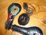
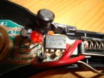
I was passing the pound store today, and I picked up a car mobile phone charger to see how it works.

Input: 12 to 24V
Output: 5.5V 500mA
Retractable cord - hence the spring in the photos. Note the circular tracks on the PCB for the brushes.

The heart of this thing is a MC34063 DC to DC convertor. No input capacitor is fitted, although there is a space for one. Anyone interested in me drawing up a schematic? It looks like a very handy chip!

A
 

Attachments

Andrew Cowan

Senior Member
Nowhere near that complex - remember, I got it from the pound store! There is no input conditioning at all - that link you posted has lots of bits and pieces.
 

hippy

Technical Support
Staff member
Well worth decoding the circuit and comparing it to the reference designs. It may be an expensive way to get a chip, but perhaps not when postage and packing are added on. It seems it can be used as a step-up and step-down DC-DC convertor. So a cheap and cheerful way to experiment.
 

MFB

Senior Member
Certainly very useful information and a good approach to see how the ‘professionals’ do it. However, I wonder if the demands on this charger are less demanding than would be required to power a raw PICAXE circuit. Because the mobile phone would have additional regulation and filtering before it’s micro. When I have tried running automotive electronics without the type of screening and filtering normally used by amateur radio operators (LC filters and feed-thru caps etc), the micro can operate very erratically due to EMI radiation.
 

chipset

Senior Member
would the chip in the phone charger be a better choice? Truthfully I dont know where to start or stop with this. Like I see a voltage regulator that can hadle all the stuff you guys warn about and then you move on lol. Which would be better to use? Comparing the data sheet for the phone charger chip against whats actually in the phone charger looks to me like thats all they are using (the basic circuit right out of the book).
 

Andrew Cowan

Senior Member
Well, here's the circuit used.

Hippy says it's an expensive way to get a chip - Once you add the cost of the inductor etc, for a one iff project, it isn't that bad.

A
 

Attachments

BeanieBots

Moderator
I'd have to advise against such a circuit.
Vcc is rated at 50v and the switch at 40v.
Those voltages are extremely likely to be exceeded in a car environment with zero suppression.
 

hippy

Technical Support
Staff member
I'm quite certain the chip would be capable of supplying a PICAXE circuit with power, though it may need some additional supply smoothing and circuit tweaking. A scope on the Vout should reveal a lot in that respect.

For automotive PSU's it's still more a question of front-end filtering and automotive rated components. There's a considerable difference between something which is an accessory which connects to the vehicle for a short period and something which is permanently attached, endures prolonged use and directly affects the vehicles operation.

A module which powers / charges a mobile phone has a lot less to worry about when it comes to failure than a design where failure can affect the operation of a vehicle. What is a suitably competant design in one circumstance is not necessarily so in another.
 

Dippy

Moderator
Chippy, ignore tangents. That is the Forum Disease. Stick with your Plan A.

Andrew's top quality device is a example of how to get away with near-tat.

Design Brief:
1. Look at Data Sheet design ref.
2. Chop out as much as possible with it working good enough.
3. Who cares if it fails. Its so cheap that people will bin it rather than bring it back under warranty - and then buy another bit of tat from our sister Company.
4. People want cheap, so give 'em cheap.
5. Quality? What's that?
6. Remember to put UL, BS, EC etc. on label.

Hippy makes a good point about things that are permanently attached to the supply vs temporary plug-ins.

Just use your original reg design with a fuse+choke+diode+ trans-supp in front of it.

Have a go.......
 

chipset

Senior Member
thanks for that post it made me chuckle a bit but its so very true. I was PM'd with a nice schematic for a power stage that includes zeners and blocking diodes along with noise suppresion caps. It is in use on a car and he says it works just fine so I think Im going to trust my judgment and go with what I think will work.

I hope the regulator I posted will help some guys and once I get it in and use it Ill let you guys know how it works.
 

BCJKiwi

Senior Member
You may wish to check out the LM2940 family as an alternative to the TI regulator - a bit simpler but with the protections etc.
 

MartinM57

Moderator
+1

...and the LM2937 family as well.

The LM29xx also seem a lot more available - the OP's regulator is a good datasheet find, but I could only track down Digikey as a supplier.
 

Dippy

Moderator
There are quite a few - enough for a Westaust table :)

But let's not put Chipset in a recursive loop or else he'll never get it done.
 
Top