Bi-Colour LED Control - one output pin?

chigley

Senior Member
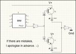
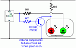
I have a green/red bi-colour common cathode LED. Normally I'd take the cathode leg to 0V through a resistor, and wire each of the anodes to its own input. I would then be able to control the colour of the LED by setting either of the anodes to high for the individual colours, or both together to make a third yellow-like colour.

My problem is that I only have one output pin left on my PICAXE to control this. The third mixed colour is not required. Is there a clever way of controlling the LED with just one output pin?

For example; if the pin is high, the red anode leg would need to be pulled to 5V and the green at 0V. If the pin is low, the green leg would need to be pulled to 5V and the red at 0V.

Thanks :)
 
Last edited:

robert beckett

New Member
Hi,
I'm pretty new to this forum, but is the answer to your question in the picaxe manual 3 - page 8?

Bi-colour LEDs often contain both green and red LEDs connected in ‘inverse parallel’.
This means if current flows one way through the device the LED lights green, and if
current flows the other way the LED lights red. Therefore by using the sink/source
capabilities of the PIC Microcontroller it is possible to light the LED in both colours.

Rob


just re-read your post - only 1 pin left! sorry
 

chigley

Senior Member
Thanks for the advice but I only have one output pin left, whereas the manual's offering requires two.

Charlie
 

eclectic

Moderator
@chigley.

Three questions please.

1. I'm assuming your LED has 3 legs R+ / Gr+ / Gnd ?
(Edit. Just seen edit to post#1)

2. Which Picaxe are you using?

3. Are you prepared to use extra components, eg transistor/diodes?

e
 

chigley

Senior Member
@chigley.

Three questions please.

1. I'm assuming your LED has 3 legs R+ / Gr+ / Gnd ?

2. Which Picaxe are you using?

3. Are you prepared to use extra components, eg transistor/diodes?

e
1. That's correct, yes.
2. 08M - all pins used apart from one output
3. Transistors/diodes are fine yes, but I don't think I'd take it as far as an IC for something aesthetic like this

Thanks
 

hippy

Ex-Staff (retired)
You actually have what is called a tri-colour LED. Bi-Colour LED's are two pin LED's with each internal LED wired in parallel and reversed as robert notes ( welcome to the PICAXE forum ).

The only way I can think of driving a tri-colour LED from a single pin is to use a PWMOUT pin, wire the two anodes together and use series capacitors for each to provide impedance at different frequencies ( I think it's Dr Acula who gets the credit for that solution from a controlling 12 LED's from an 08M question a while ago ).

For an 08M it is probably easier to change to a bi-colour LED. That can be wired to a voltage divider mid-point and controlled by output high or low or turned off by making the pin an input.
 
Last edited:

chigley

Senior Member
You actually have what is called a tri-colour LED. Bi-Colour LED's are two pin LED's with each internal LED wired in parallel and reversed as robert notes ( welcome to the PICAXE forum ).

The only way I can think of driving a tri-colour LED from a single pin is to use a PWMOUT pin, wire the two anodes together and use series capacitors for each to provide impedance at different frequencies ( I think it's Dr Acula who gets the credit for that solution from a controlling 12 LED's from an 08M question a while ago ).
Right OK, thanks for that. I think I bought it as a "bi-colour LED" so I just assumed that's what it was generically called.

The easy way of doing it would be to take the green anode to +5V permanently, and then light the red simultaneously (controlled by the PICAXE) when I want it to be red. I've used these before and have found that red colour always overpowers the green colour, such that pwmout has to be used on the red anode to create the mixed yellow colour.

This method would work (green permanently lit, red added by PICAXE when required) but I just wanted to see what suggestions were made to try and do it "properly", and to help broaden my knowledge :) There must be a way of doing it with additional components!

Charlie

EDIT: I don't really understand what you're suggesting in the edit at the bottom of your post. Could you explain it a little more please?
 

hippy

Ex-Staff (retired)
Code:
                              -.- +V
                              .|.
 PICAXE-08M         RED       |_| 1K
.----------.    .---|>|---.    |
|       X1 |----{         }----{
`----------'    `---|<|---'   .|.
                   GREEN      |_| 1K
                               |
                              -^- 0V

#Picaxe 08M
Do
   Pause 1000 : Input  1  ' Off
   Pause 1000 : High   1  ' Red
   Pause 1000 : Low    1  ' Green
   For w0 = 1 To 1000
                Toggle 1  ' Red+Green
   Next
Loop
 

QuIcK

Senior Member
what hippy is suggesting is called charlieplexing, and it it quite a cool way of driving hundreds of leds from about 15 pins.
i also like the idea of tuning each led to a frequency, then using pwmout to drive them! extremely clever clogs there!
 

westaust55

Moderator
what hippy is suggesting is called charlieplexing, and it it quite a cool way of driving hundreds of leds from about 15 pins.
i also like the idea of tuning each led to a frequency, then using pwmout to drive them! extremely clever clogs there!
But as chigley has a three terminal bi-colour LED they are not connected in reverse as per hippys sketch but in common cathode as mentioned in post 1
 

chigley

Senior Member
what hippy is suggesting is called charlieplexing, and it it quite a cool way of driving hundreds of leds from about 15 pins.
i also like the idea of tuning each led to a frequency, then using pwmout to drive them! extremely clever clogs there!
Yeah it certainly sounds clever, but I think it's overkill, and I don't understand it either :p Too much effort for something aesthetic... although if anyone wants to explain it and how/why it works, I'd enjoy to learn :)
 

eclectic

Moderator
@Chigley

Probably utterly pointless,
because it's a right faff to build and takes up a lot of space.

It is NOT meant as a solution,
but it might be useful as a learning exercise.

I pinched two circuits from here:
http://www.kpsec.freeuk.com/trancirc.htm

PNP switch, and a low-sided NPN switch.

A BC327 and a BC548. (Because they were in the toy-box.)
1K resistor
4K7 resistor
2 x IN4148 diodes

2 LED's (Cathodes connected)


Program
Code:
#picaxe 08m
main:

toggle 2
pause 1000
goto main
I repeat.
It is NOT a complete solution,
but just something to play with.

e
 

Attachments

Last edited:

QuIcK

Senior Member
http://www.instructables.com/id/SM4L0GEF1ZM4KL0/


this is my understanding:

Charlieplexing uses the clever method of making pins high-impedance. Essentially, this means disconnected, as in no current will flow to or from the pin.
A pin is a current source when high, a current sink when low, and high impedance when it is set to an input (as you wouldnt want an input to alter the characteristics of a circuit when connected, it is high impedance so virtually no current flows)

so, in the above circuit, in order to light led6, you would make pin1 high, and pin3 low. for led 5, you would make pin3 high, and pin1 low. Pretty obvious, right? but what about pin 2? if you set it either high or low, current will flow through one of the other leds, and we end up controlling more than 1 led at a time.

this is the clever bit.
Pin2 is set as an input. you dont need to read anything from it, save the value or anything, just set it as an input. This makes it high-impedance, or not-connected.
so pin3 is high and pin1 is low. I hear you exclaim that i am making this up, it'll never work... there is a path for the current to flow through led3 then led2. And your right, current will flow. But, if you were an electron, would you rather go through 2 leds to get home, or 1 led? I'd rather go through 1 led, and that what happens. The majority of current flows through led 5, not through led3 and led2.

what about led 1->4?
well, if pin3 was made an input, it becomes "not connected", so if pin1 was high and pin2 was low, led1 lights. if pin1 was low, and pin2 high, then led2 lights
if pin1 was made an input, pin 2 is high, and pin 3 is low led 4 lights, and if pin2 is low and pin 3 is high then led 3 lights.

make sense? thats 3 pins controlling 6 leds. The number of leds you can control increases pretty quickly! but so does complexity.


what hippy is suggesting is that if the pin is set high, then the led between the pin and ground will light.
if it is set low, the led between the pin and +5v will light. if it is set to input, neither will light.
 

QuIcK

Senior Member
:eek: thats a bit mental. is that charlieplexing with pwm tuning as well? i think its a lot easier to use a max7221 chip :D. mayb not as cool to brag about tho, but 64leds from 3 picaxe pins
 

eclectic

Moderator
:eek: thats a bit mental. is that charlieplexing with pwm tuning as well? i think its a lot easier to use a max7221 chip :D. mayb not as cool to brag about tho, but 64leds from 3 picaxe pins
If you want a solution, then fine: buy the correct chip.

However, for some of the clever Picaxers, (not me!),
it's a bit like the Times Crossword.

The real fun is in the solving; not the solution. :)

You're in Edinburgh. Look up Robert Louis S.
"To travel hopefully is a better thing than to arrive, and the true success is to labour."


e

Or a down-market version, is the old joke involving a hammock. :)
 
Last edited:

hippy

Ex-Staff (retired)
This is Wilf Rigter's solution...
You never cease to amaze me on how you find these links. Either you have an astounding memory, good fortune with search criteria, or are employed by Megadodo Publications (HHGTTG) :)

I've updated the code tags in the original link.
 

eclectic

Moderator
You never cease to amaze me on how you find these links. Either you have an astounding memory, good fortune with search criteria, or are employed by Megadodo Publications (HHGTTG) :)

I've updated the code tags in the original link.
I was close.
post #41

101010 :))

e
 

QuIcK

Senior Member
stop geeking out guys :rolleyes:
Im just jealous that I never think about these things. I just think, hey.. pwm, thats intensity control, mayb a clock generator... kewl.
I'm gonna store this nugget of information, and whip it out to astound and amaze people in the near future!
 

inglewoodpete

Senior Member
Simple solution

I assume that there will always be 1 LED on ie never a 'fully off' state. You mention 2 states (originally red and green).

One option is to have 1 anode (red?) simply connected to +5v via a resistor (say 330 or 1000 ohms). Then connect the other anode to the PICAXE output via a second, similar sized, resistor. O/P low = Red. O/P high = Yellowish.

If you insist on Red/Green, the second option is to use the same circuit as above but add a resistor (try 4.7k) and small signal NPN (BC548/PN100 etc). PICAXE O/P to resistor to base. Emitter to 0v. Collector to junction of red anode and resistor.

A high on the PICAXE output would turn the green led on and turn the NPN 'on', bypassing the red LED's current, turning it off. A low o/p would leave the red LED on.

Maybe I'll draw a schematic later. I did! I did!
 

Attachments

Last edited:
Top