Capacitance meter

russbow

Senior Member
Has anyone had experience of a picaxe based digital capacitance meter.
I have searched the forums but with no solid result'

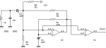
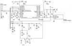
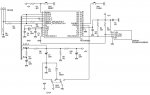
There is a nice one here http://ironbark.bendigo.latrobe.edu.au/~rice/lc/ Unfortunatly PIC not PicAxe. The ASM code is provided but needs another type of programmer. Just some pointers to find further ideas would be helpful. 73s Russ
 

eclectic

Moderator
@russbow
I looked at a Picaxe capacitor analyser a couple of years ago.

It might be possible, but only over a very limited range.
(I would love to be proved wrong.)

However, I'm lazy, gave up, and bought a Peak-atlas lcr

AFAIK, there's been no further published info.

e

PS
On a separate topic, have you seen this serious use
of a Picaxe, for Ham use?

http://www.users.on.net/~endsodds/analsr.htm
 

eclectic

Moderator
@Russ
A.
Also, have a look at
http://www.engj.ulst.ac.uk/sidk/PIC/Tips 'n Tricks.pdf

B.
And another thought.
Using Pwmout, (along with a few bits of Jiggery-pokery),
can provide frequencies, at present, ranging from

8MHz -- ~ 250 Hz

resistors / potentiometers are cheap.
All larger Picaxes have readadc.


C.
You're a Ham. You know all about accepter/ rejecter circuits.

Go on Russ,
design one and put it in the finished Projects section. :)

e
 

russbow

Senior Member
EC, nice bit of kit. Had a look at the programme - way beyond my current understanding. Not really on my wish list though as I have a nice MFJ analyser.

A. Yes, picked up the link earlier. There are a couple of cute designs out there that use a DVM as display. Basically done with a couple of 74 series chips. 2 similar designs for capacitance and inductance. I think thay lend themselves to easy interfacing to a picaxe. After all they only offer a "calibrated" voltage out. One pic, one LCD, one plastic box - result.

I do like the idea of the circuit with the 16F84 though. Guess I'll program a chip with the homebrew "JDM" and if it reads back OK breadboard the rest.
 

hippy

Technical Support
Staff member
I did build a sort of capacitance meter and it worked quite well over a fairly wide range but it wasn't completed.

This used a Schmitt Trigger input with the cap in an RC configuration and Timer2 (?) to time how long it took for the cap to charge and discharge. I discharged to 'low' input, started the timer, charge to 'high' and stopped the timer. Results were (surprisingly) very consistent.

To handle various sized capacitors I poked OSCCON and the timer's pre-scalers etc to get fast tick rates so could increase time resolution for smaller caps, and slow for larger caps without getting timer overflows.

Never converted "time" to capacitance and never tested what the maximum C would be. It worked well in the 1nF to 1000uF range from recollection.

The only code I have is attached.
 

Attachments

hippy

Technical Support
Staff member
I was a bit brief on the specs there :)

That was an 08M, all on bread-board and I saw no problems with stray capacitance. Two resistors ( slow and fast charge - just slow used in that code ) and that's it.

The idea was to measure time from Vx to Vy, send that to a PC and have it do the maths. It auto-calibrates the time measuring loop when there's no cap in place ( fit between the R/input and 0V ), but PC would need to be calibrated with two known value C's.

The rationale for me was to determine what standard value a cap was, rather than what exact capacitance it had. Just to save squinting as I went through my box of mixed caps while sorting them into drawers.
 

Dippy

Moderator
It's a useful technique. I used a similar method in PICs when I had run out of ADC inputs, but I was using it for measuring a thermistor and having a fixed capacitor.
Obv the R & C function can be swapped.

It's very similar (almost identical) to the method used in Basic Stamp "RCTime".
 

MFB

Senior Member
Dual-slope measurement?

It might be worth considering some form of dual-slope technique, as used by some ADC chips. This could be achieved by counting up whilst charging a reference capacitor, through a resistor, and then reversing the count whilst discharging the external capacitor. The value of the unknown external capacitor could then be derived from the difference in the count.

This technique has the advantage that drift in the supply voltage, Schmitt threshold level and charging/discharging resistor are all cancelled out. However, the reference capacitor must be a high tolerance type, like polycarbonate.
 

Milos

Member
LC-meter

I have just finished the breadboard version of my LC-meter. It works quite well with AXE200 module and I am going to build the final version with 28X2 (new one - 64 MHz). I use built-in comparators. My LC-meter consists of the chip and a few parts around. I am ready to share my experience : my schematics and code too.
 

Janne

Senior Member
Has anyone thought about using the picaxe timer in counter mode, and use an LC resonant circuit to measure the capacitance? Plus side is, that it would be possible to use the same arrangement for measuring an inductor too. I don't know if it's possible to find out the contents of the 16 bit timer by peeking into the SFR, but that would be crucial in the task.

A sum of the peeked timer value + number of overflows * 65536("timer" variable) could then be used to figure out the total count of pulses during the measurement perioid, and from that value the component value could be calculated.

The LC resonant hardware could be the same as in this project:
http://www.cappels.org/dproj/nlglcm/Pretty%20Good%20LC%20Meter%20Project.html
 

hippy

Technical Support
Staff member
I'm sure I saw a recent post on this forum for an L-C meter using COUNT and those could be modified to use hardware timers as counters.
 

John West

Senior Member
I like the idea of a capacitance meter using an inductor for a resonant frequency measurement, as opposed to a simple RC depletion measurement. It provides more relevant info.

I used a cheap RC type meter to determine the capacitance of my longwave antenna (170 kHz) and ended up having to completely rewind a 15 kg loading coil after determining the original capacitance measurement of the antenna was off by half.

As was mentioned previously, there are a number of dirt-cheap capacitance meters, so I suspect there's no particular reason to turn a PICAXE into another one. However, a GOOD inexpensive capacitance meter that implements the obvious advantages of a PICAXE would be highly welcome.

Measuring the capacitance at various frequencies to get an idea of other characteristics, and displaying the data on an LCD would be something the PICAXE cap meter would be able to do that the cheapo meter circuits presently available could not.

Of course, the measurement of inductors with such a circuit is just as easy by swapping places between the LC's inductor and capacitor.

Simply put, a PICAXE could do far more and better for next to nothing in cost, if it were well designed. I'm tired of looking at the insides of expensive LCR meters and seeing very little that an 18M2 couldn't handle.

That's a likely project for an ingenious PICAXE guru to take on if they have some free time.

Used in conjunction with womai's PICAXE based "simplescope" a newbie would be modestly well equipped to tackle a wide variety of electronics projects for next to no investment in test equipment.

I bring this up because I recall as a youth that the expense of those two pieces of test equipment was a major impediment to my early experimenting, and it would be a very good thing to see such a wall torn down for the benefit of future experimenters of any age.
 

eclectic

Moderator
Snipped
Used in conjunction with womai's PICAXE based "simplescope" a newbie would be modestly well equipped to tackle a wide variety of electronics projects for next to no investment in test equipment.

I bring this up because I recall as a youth that the expense of those two pieces of test equipment was a major impediment to my early experimenting, and it would be a very good thing to see such a wall torn down for the benefit of future experimenters of any age.
Well said John.
I'm now fortunate enough to own some
"middle" band equipment,
but until very recently,
there was very little "pocket-money"
equipment about.

e
 

John West

Senior Member
Further soapbox commentary:

As pieces of test equipment, capacitance and inductance meters are seldom used and hardly worth the investment for even companies doing most electronics R&D. At Sony's data storage lab, I had a room full of hundred's of thousand's of dollars worth of test equipment. But no LCR meter. Didn't need one.

However, as a poor kid with a pile of unreadable capacitors and inductors, and various other unidentifiable components pulled from the chassis' of old radios and TV's, I needed one desperately, but didn't have one and couldn't afford one.

Scroungers of cheap or free surplus parts are the folks who really need a good LC meter. Wild-eyed experimenters with ideas for bizarre electronics contraptions are, too.

The folks who need a decent LC meter are the very folks who can't afford one. Like womai's new o'scope design, I think the creation of a good, nearly free, PICAXE based LC meter would be a real service to the electronics hobbyist community.
 

Milos

Member
My LC-meter works. I am including the PEBBLE configuration file. I think that it is good enough as your first step to your own development. Cx is connected in paralell to the 1800 pF capacitor or Lx in serial to the 470 uH coil instead of wire jumper. Blue wires connecting B.0 and B.1 to ground are removed or placed to switch between calibration/Cx/Lx. In final version it will be done by a switch. I can mail my code if wanted.
 

Attachments

Last edited:

eclectic

Moderator
My LC-meter works. I am including the PEEBLE configuration file. I think that it is good enough as your first step to your own development. Cx is connected in paralell to the 1800 pF capacitor or Lx in serial to the 470 uH coil instead of wire jumper. Blue wires connecting B.0 and B.1 to ground are removed or placed to switch between calibration/Cx/Lx. In final version it will be done by a switch. I can mail my code if wanted.
Can you please post a schematic,
for those who do not use Pebble.

And please also post the code.

e
 

Milos

Member
To Eclectic:

The schematics of the oscillator is nearly all. I do not know how to attach larger pictures. I will try to explain it in words. My breadboard version is built around the AXE200 module. The two 10M capacitors are tantalum ones. There is another 22M blocking +5V above the top 100K resistor. There are two wires from C.3 and C.4 to the display - i2c bus - with two 4.7K pullup resistors. I have put a blocking capacitor 150 nF between legs 25 (+5V) and 27 (0V). Pins B.0 and B.1 are or are not connected to ground by wires - their function should be clear from my code. The "weak" pullup is activated on port B. C0 should be of good quality - polystyrene one, no ceramic. L0 is a standard 470 uH coil.

Any question more?
 

Milos

Member
Sorry

Dear friends,
there is a little error in my PEBBLE file. The blocking 150 nF capacitor is between legs 25/27 in fact. Use the new file, please.
 

Attachments

Milos

Member
New version

I did another step to the final version. I am still on my breadboard, but I exchanged AXE200 module for 28X2 (PIC 18F25K22 at 64 MHz, firmware B.3). I am including full schematics because I think that it is complete now.
 

Attachments

eclectic

Moderator
I did another step to the final version. I am still on my breadboard, but I exchanged AXE200 module for 28X2 (PIC 18F25K22 at 64 MHz, firmware B.3). I am including full schematics because I think that it is complete now.
Thank you Milos.
Can you please enlarge the schematic.
It is too small to see at 17 KB
 

Milos

Member
Schematics

I tried to upload it uncompressed but I was told that my picture is too large. I will send it to you as a private message.
 

John West

Senior Member
Thanks, Milos. That's a lot of code, but very well commented. I'll build the circuit, then go through the code and see if I can get it all running and talking to my LCD.

However, I'm not familiar with your component nomenclature. What do the M values mean in regards to capacitors, microfarad? And what is the value of the C0 capacitor labeled 1K2?
 
Last edited:

Milos

Member
Sorry - I used nomenclature common here.
Capacitors - 22M means 22 microFarads. 1M5 would mean 1,5 micro.
Capacitor 1K2 = 1200 pF. Resistors: 4K7 = 4,7 kiloOhms, 100K = M1 = 100 kiloOhms. Basic units are pF and Ohms. K and M mean multipliers and are used instead of comma too.
I used display I bought in the HobbyRobot shop in Prague. I guess you will need to change the subroutines dealing with the display - initDisplay, clearDisplay, displayString.
I recommend reading the pages about LC-meter with PIC 16F628. See link in my post #25.
If you have a question - ask.
 
Top